Implementing a Buck converter in RTL.
FPGAs are great devices to make math and, fortunately, almost all in this world are maths so, can we implement anything on an FPGA? Uhh I wouldn’t like to say yes fastly but, maybe… In this blog, we saw how we can implement physical models on an FPGA using MATLAB and Speedgoat, but on that occasion, we needed a real-time target machine and a bunch of MATLAB packages that not everybody has access to. In this post, we are going to make something similar, but with big differences, I mean. I am going to show you how we can implement a physical model into an FPGA, but this time calculating the equations of the model. Relax!, we are not going to deal with very difficult equations, but using this method, we are going to need a strong knowledge about the system we are going to simulate. The model will be an ideal Buck power supply, and the word ideal is important because we are not going to manage the non-linear effects or the imperfections of the elements of the model. So, if you are not scared about math, let’s go.
First of all, we need to translate the components of the Buck power supply into a set of blocks or mathematical expressions to, later, convert them into an RTL code. The Buck power supply has the configuration shown in the next figure, and we must notice that the model has two different parts, the filter, which is a linear circuit, and the switching cell, which is not linear in all the range, but we can say that it has two linear behaviors, one when the switch is closed, and another one when the switch is open, so we can say that this part of the circuit is piecewise linear.

With that circuit in mind, the next is to identify the variables of the circuit, in particular the state variables that will change its behavior whenever the input state changes. For a power supply like this, we can identify the inductor voltage and inductor current, the capacitor current, and the output voltages and current. Knowing the state of these state variables, we can know also the next value of them.

Now comes the most exciting part, the behavior of all of these state variables are defined by equations, so we need to know those equations. Let’s start with the inductor voltage, which is the easiest.
\[v_L = v_i(t) - v_o(t)\]Also, we can define the inductor voltage from the inductor current.
\[v_L=L \cdot \frac{di_L}{dt}\]Therefore, using these two equations, we can obtain the inductor current equation.
\[\frac{di_L}{dt}=\frac{v_i(t)-v_o(t)}{L}\]Now, integrating both sides of the equation, we have
\[i_L = \frac{1}{L} \int v_i(t)-v_o(t) dt\]The next is the capacitor. Notice that the voltage of the capacitor is the same as the output voltage, so the equation is the next
\[v_o(t) = \frac{1}{C} \int i_c(t) dt\]The current through the capacitor can be calculated as follows
\[i_C = i_L - i_O\]Finally, the output current, which is the current that flows for the output resistor is
\[i_o = \frac{v_o(t)}{R}\]with all of these equations, we can build the next model using Simulink.

now, we can simulate this model, and check its behavior. I run the model using a MATLAB script in order to plot the signals and, later, compare the signals with the RTL model response.
close all
clear all
clc

%% initialize model

L = 200e-6;
C = 660e-6;
R = 10;
vin = 24;
fsw = 15e3;
duty_cycle = 0.25;

%% Execute simulation
data = sim("model_block.slx");

%% Read signals

il = data.simout(:,1);
vo = data.simout(:,2);

figure
plot(data.tout, vo)
title("Output voltage")

figure
plot(data.tout, il)
title("Inductor current")
Executing this script, we will obtain the next waveforms for the output voltage and the inductor current.

With these results, you must notice two different effects. The first one, the model has a huge resonance. When we apply a fixed duty cycle, the system has a resonance during the first 50 ms. This resonance is due to the output filter. A Buck converter has an LC filter in the output which has the next response.
s = tf('s');
wn = 1/(sqrt(L*C));
Q = R*sqrt(C/L);
fc = wn/2/pi

hf = wn^2/(s^2+wn/Q*s+wn^2);

figure
bode(hf)

We can see that the filter has a gain in its natural frequency, so applying a step, which contains many different frequencies, we can excite the resonance. In a real Buck power supply, this effect is reduced due to the inductor series resistor and the capacitor series resistor. The model I have developed is a very simple model, only with the basic elements, but in reality, the inductor has a series resistance, so, for example, the equation of the inductor voltage will be the next
\[v_L=L \cdot \frac{di_L}{dt} + r_L i_L\]To keep the model simple, we can eliminate these elements but making this has those effects. The effect can also be reduced by using a duty cycle ramp instead of a step.
The second effect that we can notice is that the inductor current can be negative, which with a real Buck power supply it is impossible since the switch is opened and the diode is blocking. To make this possible, we can replace the diode by another switch, converting the buck power supply into a synchronous Buk power supply, and making possible negative current through the inductor. In a real Buck converter, the current will be zero when it has to be negative. This is known as discontinuous conduction.

Then, we have the model in Simulink working properly, so the next is to translate this model into an RTL code. First, we need to replace the continuous integrators by discrete integrators and join the constants to reduce the number of operations. The diagram that we will implement in RTL is the next.

Now it is time to write Verilog code. As I mentioned, we are going to mix the constants and pre-calculate them, so the inputs of the model, besides clock, reset and clock_enable, will be the input voltage, the result of the division \(\frac{T_{PWM}}{L}\), the result of \(\frac{T_{PWM}}{C}\) and the result of \(\frac{1}{R}\). The outputs of the model will be all the state variables.
module buck_v1_0 #(
  parameter model_data_width = 25,
  parameter model_decimal_width = 15
)(
  input aclk,
  input resetn,
  input clock_enable,

  input pwm,
  input signed [model_data_width-1:0] input_voltage,
  input signed [model_data_width-1:0] period_inductor,
  input signed [model_data_width-1:0] period_capacitor,
  input signed [model_data_width-1:0] inverse_resistor,

  output reg signed [model_data_width-1:0] inductor_current,
  output signed [model_data_width-1:0] capacitor_current,
  output signed [model_data_width-1:0] output_current,
  output reg signed [model_data_width-1:0] output_voltage
);
Regarding the input voltage, we are going to simplify the switching cell to something similar to the next diagram.

And finally, the Verilog code that implements the model of the Buck converter is the next.
  /* voltage difference */
  assign voltage_diff = pwm? input_voltage - output_voltage: -output_voltage;

  /* inductor integrator gain */
  assign voltage_diff_intl_2width = voltage_diff * period_inductor;
  assign voltage_diff_intl = voltage_diff_intl_2width >>> model_decimal_width;

  /* inductor integrator */
  always @(posedge aclk)
    if (!resetn)
      inductor_current <= 0;
    else
      if (clock_enable)
        inductor_current <= inductor_current + voltage_diff_intl;

  assign capacitor_current = inductor_current - output_current;

  /* capacitor integrator gain */
  assign capacitor_current_intc_2width = capacitor_current * period_capacitor;
  assign capacitor_current_intc = capacitor_current_intc_2width >>> model_decimal_width;

  /* capacitor integrator */
  always @(posedge aclk)
    if (!resetn)
      output_voltage <= 0;
    else
      if (clock_enable)
        output_voltage <= output_voltage + capacitor_current_intc;

  /* resize output current */
  assign output_current_2width = output_voltage * inverse_resistor;
  assign output_current = output_current_2width >>> model_decimal_width;
To calculate the value of the constants, I used this Python script.
Vin = 24
L = 200e-6
C = 660e-6
R = 10

fs = 500e3
T = 1/fs

nDecBits = 16

v_code = int(24 * 2**nDecBits)
l_code = int(T/L * 2**nDecBits)
c_code = int(T/C * 2**nDecBits)
r_code = int(1/R * 2**nDecBits)

print(v_code)
print(l_code)
print(c_code)
print(r_code)
I have developed also a module to generate a PWM signal in order to test the Verilog module. Now, we can execute the testbench using Icarus Verilog and the next script
iverilog ../test/buck_test.sv ../source/pwm_generator.v ../source/buck_v1_0.v -s buck_test -o ./sim.vvp
vvp sim.vvp
rm ./sim.vvp
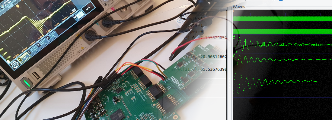
Now, on GTKWave we can check that the model response is pretty similar to the Simulink response, and, for an input voltage of 24 volts, and a duty cycle of 25%, the output voltage is 6 volts, which is the expected voltage.

Now, since I want to compare the RTL model and the Simulink model, I have added the next code to the testbench to generate a csv file with the inductor current and the output voltage.
  /* output file */
  initial
    begin
      file_id = $fopen("data.csv","w");

      $fwrite(file_id, "time, inductor_current, output_voltage \n");

      forever begin
        @(posedge clock_enable);
        $fwrite(file_id, "%f, %d, %d \n", $time*`base_time, inductor_current, output_voltage);
      end

    end
Finally, reading this file from MATLAB, we can plot the RTL response with the Simulink response and compare them.
%% read simulation data

rtl_data = csvread("../script/data.csv", 1,0);

rtl_time = rtl_data(:,1);
rtl_inductor_current = rtl_data(:,2) / 2^16;
rtl_output_voltage= rtl_data(:,3) / 2^16;

%% compare data

figure;
plot(data.tout, vo)
hold on
plot(rtl_time, rtl_output_voltage)
xlim([0, 0.2])
legend("Simulink", "RTL")

We can see that both responses are pretty similar, so now, we do not have an RTL code, but a Buck power supply ;). We can use this module to test control algorithms in simulation, or, even best, we can use this model running in a development board with a DAC to test a control algorithm implemented in any other hardware device.
In this blog, we have talked about hardware in the loop, and what we have developed in this post is similar, but it is not the same. In this example, we have written a solved circuit in Verilog, and using Speedgoat, we write the space-state model and the solver runs on the FPGA. Despite that, if we need to run simple models like an ideal Buck converter or a Boost converter, and we have strong knowledge about how this converter works, implementing a model like this in RTL is a very interesting project.
All the code of this project is uploaded to Github