FFT algorithm using an FPGA and XDMA.
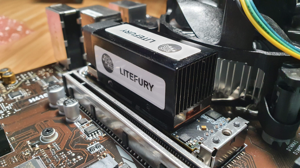
In this blog we talked (a little) about the xDMA IP from Xilinx, and how to send and receive data through PCI using an FPGA. On that occasion, we used the Picozed board with the FMC Carrier gen 2. This time the board used Litefury from RHS research. This board is the same as the ACORN CLE-215, and is based on the Artix7 piece XC7A100T. The board has a M.2 format, therefore has 4 PCI Express Lanes, with a speed of up to 6.6 Gbps (GTP transceivers). The M.2 format make this board an excellent choice to be integrated into our working PC in order to test different algorithm without the need of connecting external hardware. The board has a connector with the JTAG pins, but we can also debug our design using Xilinx Virtual Cable accessible through the xDMA IP. In this post, we will use this board to execute an FFT algorithm, and then we will compare its performance with the same algorithm executed on the PC. The use of a Xilinx IP to perform this kind of algorithm has advantages, we do not need to develop it, but also it has son disadvantages because we can not optimize the interfaces in order to improve their performance.
Unlike the previous post, in this post we will use the xDMA drivers for Linux provided by Xilinx. The use of these drivers makes easy access to the DMA channels of the DMA/Bridge Subsystem for PCI Express.
To install the drivers, first of all, we need to clone the repository.
~$ git clone https://github.com/Xilinx/dma_ip_drivers.git
Now, in the repository folder, we need to navigate to the /xdma folder.
~$ cd dma_ip_drivers/XDMA/linux-kernel/xdma/
In this folder, according to the instructions that we can find in the readme.md file, we need to execute the make install command. In some cases, the output for this command will be the next.
~/dma_ip_drivers/XDMA/linux-kernel/xdma$ sudo make install
Makefile:10: XVC_FLAGS: .
make -C /lib/modules/5.11.0-27-generic/build M=/home/pablo/dma_ip_drivers/XDMA/linux-kernel/xdma modules
make[1]: Entering directory '/usr/src/linux-headers-5.11.0-27-generic'
/home/pablo/dma_ip_drivers/XDMA/linux-kernel/xdma/Makefile:10: XVC_FLAGS: .
  CC [M]  /home/pablo/dma_ip_drivers/XDMA/linux-kernel/xdma/libxdma.o
  CC [M]  /home/pablo/dma_ip_drivers/XDMA/linux-kernel/xdma/xdma_cdev.o
  CC [M]  /home/pablo/dma_ip_drivers/XDMA/linux-kernel/xdma/cdev_ctrl.o
  CC [M]  /home/pablo/dma_ip_drivers/XDMA/linux-kernel/xdma/cdev_events.o
  CC [M]  /home/pablo/dma_ip_drivers/XDMA/linux-kernel/xdma/cdev_sgdma.o
  CC [M]  /home/pablo/dma_ip_drivers/XDMA/linux-kernel/xdma/cdev_xvc.o
  CC [M]  /home/pablo/dma_ip_drivers/XDMA/linux-kernel/xdma/cdev_bypass.o
  CC [M]  /home/pablo/dma_ip_drivers/XDMA/linux-kernel/xdma/xdma_mod.o
  CC [M]  /home/pablo/dma_ip_drivers/XDMA/linux-kernel/xdma/xdma_thread.o
  LD [M]  /home/pablo/dma_ip_drivers/XDMA/linux-kernel/xdma/xdma.o
/home/pablo/dma_ip_drivers/XDMA/linux-kernel/xdma/Makefile:10: XVC_FLAGS: .
  MODPOST /home/pablo/dma_ip_drivers/XDMA/linux-kernel/xdma/Module.symvers
  CC [M]  /home/pablo/dma_ip_drivers/XDMA/linux-kernel/xdma/xdma.mod.o
  LD [M]  /home/pablo/dma_ip_drivers/XDMA/linux-kernel/xdma/xdma.ko
make[1]: Leaving directory '/usr/src/linux-headers-5.11.0-27-generic'
make -C /lib/modules/5.11.0-27-generic/build M=/home/pablo/dma_ip_drivers/XDMA/linux-kernel/xdma modules_install
make[1]: Entering directory '/usr/src/linux-headers-5.11.0-27-generic'
  INSTALL /home/pablo/dma_ip_drivers/XDMA/linux-kernel/xdma/xdma.ko
At main.c:160:
- SSL error:02001002:system library:fopen:No such file or directory: ../crypto/bio/bss_file.c:69
- SSL error:2006D080:BIO routines:BIO_new_file:no such file: ../crypto/bio/bss_file.c:76
sign-file: certs/signing_key.pem: No such file or directory
  DEPMOD  5.11.0-27-generic
Warning: modules_install: missing 'System.map' file. Skipping depmod.
make[1]: Leaving directory '/usr/src/linux-headers-5.11.0-27-generic'
We can see that the command returns some errors regarding the SSL, and also with depmod command. First, let’s fix the SSL error. If you have this error, is because Linux, in order to improve its security, requires that all the modules that you install will be signed. In this case, these modules are not signed. The make command will try to sign the module but it cannot find the key to do it, so we need to generate a key to allow the make command fix the module and install it. To do that, we must navigate to certs/ folder, and generate the signing_key.pem file using Openssl. Before generating the key, we will create a config file named x509.genkey in /certs folder.
~$ cd /lib/modules/$(uname -r)/build/certs
~$ sudo nano x509.genkey
The content of this file must be the next.
/lib/modules/5.11.0-36-generic/build/certs$ cat x509.genkey
[ req ]
default_bits = 4096
distinguished_name = req_distinguished_name
prompt = no
string_mask = utf8only
x509_extensions = myexts

[ req_distinguished_name ]
CN = Modules

[ myexts ]
basicConstraints=critical,CA:FALSE
keyUsage=digitalSignature
subjectKeyIdentifier=hash
authorityKeyIdentifier=keyid
Once this file is created, we can generate the key files using this file as a config file.
/lib/modules/5.11.0-36-generic/build/certs$ sudo openssl req -new -nodes -utf8 -sha512 -days 36500 -batch -x509 -config x509.genkey -outform DER -out signing_key.x509 -keyout signing_key.pem
Generating a RSA private key
.................................++++
...................................................................................................++++
writing new private key to 'signing_key.pem'
-----
Once the command is executed, we can check that the files are created in the same folder.
/lib/modules/5.11.0-36-generic/build/certs$ ls
Kconfig  Makefile  signing_key.pem  signing_key.x509  x509.genkey
When the key files are created, we can return them to the /xdma folder in the downloaded repository. Now, the second issue that make the command returned to us was regarding the depmod command. This command is included in the make install command, but also can be included next to this command. We can execute depmod -a` after making the install, or we can add it to Makefile. if you choose this second option, the content of Makefile will be the next.
~/dma_ip_drivers/XDMA/linux-kernel/xdma$ cat Makefile
SHELL = /bin/bash
ifneq ($(xvc_bar_num),)
	XVC_FLAGS += -D__XVC_BAR_NUM__=$(xvc_bar_num)
endif

ifneq ($(xvc_bar_offset),)
	XVC_FLAGS += -D__XVC_BAR_OFFSET__=$(xvc_bar_offset)
endif

$(warning XVC_FLAGS: $(XVC_FLAGS).)

topdir := $(shell cd $(src)/.. && pwd)

TARGET_MODULE:=xdma

EXTRA_CFLAGS := -I$(topdir)/include $(XVC_FLAGS)
#EXTRA_CFLAGS += -D__LIBXDMA_DEBUG__
#EXTRA_CFLAGS += -DINTERNAL_TESTING

ifneq ($(KERNELRELEASE),)
	$(TARGET_MODULE)-objs := libxdma.o xdma_cdev.o cdev_ctrl.o cdev_events.o cdev_sgdma.o cdev_xvc.o cdev_bypass.o xdma_mod.o xdma_thread.o
	obj-m := $(TARGET_MODULE).o
else
	BUILDSYSTEM_DIR:=/lib/modules/$(shell uname -r)/build
	PWD:=$(shell pwd)
all :
	$(MAKE) -C $(BUILDSYSTEM_DIR) M=$(PWD) modules

clean:
	$(MAKE) -C $(BUILDSYSTEM_DIR) M=$(PWD) clean
	@/bin/rm -f *.ko modules.order *.mod.c *.o *.o.ur-safe .*.o.cmd

install: all
	$(MAKE) -C $(BUILDSYSTEM_DIR) M=$(PWD) modules_install
	depmod -a <--- THIS LINE CHANGES
endif
Once these changes are done, executing again the make install command will return the next output.
~/dma_ip_drivers/XDMA/linux-kernel/xdma$ sudo make install
Makefile:10: XVC_FLAGS: .
make -C /lib/modules/5.11.0-36-generic/build M=/home/pablo/dma_ip_drivers/XDMA/linux-kernel/xdma modules
make[1]: Entering directory '/usr/src/linux-headers-5.11.0-36-generic'
/home/pablo/dma_ip_drivers/XDMA/linux-kernel/xdma/Makefile:10: XVC_FLAGS: .
  CC [M]  /home/pablo/dma_ip_drivers/XDMA/linux-kernel/xdma/libxdma.o
  CC [M]  /home/pablo/dma_ip_drivers/XDMA/linux-kernel/xdma/xdma_cdev.o
  CC [M]  /home/pablo/dma_ip_drivers/XDMA/linux-kernel/xdma/cdev_ctrl.o
  CC [M]  /home/pablo/dma_ip_drivers/XDMA/linux-kernel/xdma/cdev_events.o
  CC [M]  /home/pablo/dma_ip_drivers/XDMA/linux-kernel/xdma/cdev_sgdma.o
  CC [M]  /home/pablo/dma_ip_drivers/XDMA/linux-kernel/xdma/cdev_xvc.o
  CC [M]  /home/pablo/dma_ip_drivers/XDMA/linux-kernel/xdma/cdev_bypass.o
  CC [M]  /home/pablo/dma_ip_drivers/XDMA/linux-kernel/xdma/xdma_mod.o
  CC [M]  /home/pablo/dma_ip_drivers/XDMA/linux-kernel/xdma/xdma_thread.o
  LD [M]  /home/pablo/dma_ip_drivers/XDMA/linux-kernel/xdma/xdma.o
/home/pablo/dma_ip_drivers/XDMA/linux-kernel/xdma/Makefile:10: XVC_FLAGS: .
  MODPOST /home/pablo/dma_ip_drivers/XDMA/linux-kernel/xdma/Module.symvers
  CC [M]  /home/pablo/dma_ip_drivers/XDMA/linux-kernel/xdma/xdma.mod.o
  LD [M]  /home/pablo/dma_ip_drivers/XDMA/linux-kernel/xdma/xdma.ko
make[1]: Leaving directory '/usr/src/linux-headers-5.11.0-36-generic'
make -C /lib/modules/5.11.0-36-generic/build M=/home/pablo/dma_ip_drivers/XDMA/linux-kernel/xdma modules_install
make[1]: Entering directory '/usr/src/linux-headers-5.11.0-36-generic'
  INSTALL /home/pablo/dma_ip_drivers/XDMA/linux-kernel/xdma/xdma.ko
  DEPMOD  5.11.0-36-generic
Warning: modules_install: missing 'System.map' file. Skipping depmod.
make[1]: Leaving directory '/usr/src/linux-headers-5.11.0-36-generic'
depmod -a
Now we must navigate to /tools folder and execute again the make command.
~/dma_ip_drivers/XDMA/linux-kernel/xdma$ cd ../tools/
pablo@mark1:~/dma_ip_drivers/XDMA/linux-kernel/tools$ make
cc -c -std=c99 -o reg_rw.o reg_rw.c -D_FILE_OFFSET_BITS=64 -D_GNU_SOURCE -D_LARGE_FILE_SOURCE
cc -o reg_rw reg_rw.o
cc -c -std=c99 -o dma_to_device.o dma_to_device.c -D_FILE_OFFSET_BITS=64 -D_GNU_SOURCE -D_LARGE_FILE_SOURCE
In file included from /usr/include/assert.h:35,
                 from dma_to_device.c:13:
/usr/include/features.h:187:3: warning: #warning "_BSD_SOURCE and _SVID_SOURCE are deprecated, use _DEFAULT_SOURCE" [-Wcpp]
  187 | # warning "_BSD_SOURCE and _SVID_SOURCE are deprecated, use _DEFAULT_SOURCE"
      |   ^~~~~~~
cc -lrt -o dma_to_device dma_to_device.o -D_FILE_OFFSET_BITS=64 -D_GNU_SOURCE -D_LARGE_FILE_SOURCE
cc -c -std=c99 -o dma_from_device.o dma_from_device.c -D_FILE_OFFSET_BITS=64 -D_GNU_SOURCE -D_LARGE_FILE_SOURCE
In file included from /usr/include/assert.h:35,
                 from dma_from_device.c:13:
/usr/include/features.h:187:3: warning: #warning "_BSD_SOURCE and _SVID_SOURCE are deprecated, use _DEFAULT_SOURCE" [-Wcpp]
  187 | # warning "_BSD_SOURCE and _SVID_SOURCE are deprecated, use _DEFAULT_SOURCE"
      |   ^~~~~~~
cc -lrt -o dma_from_device dma_from_device.o -D_FILE_OFFSET_BITS=64 -D_GNU_SOURCE -D_LARGE_FILE_SOURCE
cc -c -std=c99 -o performance.o performance.c -D_FILE_OFFSET_BITS=64 -D_GNU_SOURCE -D_LARGE_FILE_SOURCE
cc -o performance performance.o -D_FILE_OFFSET_BITS=64 -D_GNU_SOURCE -D_LARGE_FILE_SOURCE
This command will return some warnings but we can continue with them without problems. Finally, we need to load the driver with modprobe command.
~/dma_ip_drivers/XDMA/linux-kernel/tools$ sudo modprobe xdma
Now, we must navigate to /tests folder and execute the script /.load_driver with sudo privileges.
~/dma_ip_drivers/XDMA/linux-kernel/tests$ sudo su
root@mark1:/home/pablo/dma_ip_drivers/XDMA/linux-kernel/tests# source ./load_driver.sh
xdma                   86016  0
Loading xdma driver...
The Kernel module installed correctly and the xmda devices were recognized.
 DONE
If we check the list of kernel nodes in /dev, we will see a group of xdma nodes created.
~/dma_ip_drivers/XDMA/linux-kernel/tools$ ls /dev
autofs           fuse       loop10        nvram     stderr  tty21  tty38  tty54      ttyS11  ttyS28   vcs2   vcsu6            xdma0_events_4
block            gpiochip0  loop11        port      stdin   tty22  tty39  tty55      ttyS12  ttyS29   vcs3   vfio             xdma0_events_5
bsg              hpet       loop2         ppp       stdout  tty23  tty4   tty56      ttyS13  ttyS3    vcs4   vga_arbiter      xdma0_events_6
btrfs-control    hugepages  loop3         psaux     tty     tty24  tty40  tty57      ttyS14  ttyS30   vcs5   vhci             xdma0_events_7
bus              hwrng      loop4         ptmx      tty0    tty25  tty41  tty58      ttyS15  ttyS31   vcs6   vhost-net        xdma0_events_8
char             i2c-0      loop5         ptp0      tty1    tty26  tty42  tty59      ttyS16  ttyS4    vcsa   vhost-vsock      xdma0_events_9
console          i2c-1      loop6         pts       tty10   tty27  tty43  tty6       ttyS17  ttyS5    vcsa1  xdma0_c2h_0      xdma0_h2c_0
core             i2c-2      loop7         random    tty11   tty28  tty44  tty60      ttyS18  ttyS6    vcsa2  xdma0_control    xdma0_user
cpu              i2c-3      loop8         rfkill    tty12   tty29  tty45  tty61      ttyS19  ttyS7    vcsa3  xdma0_events_0   xdma0_xvc
cpu_dma_latency  i2c-4      loop9         rtc       tty13   tty3   tty46  tty62      ttyS2   ttyS8    vcsa4  xdma0_events_1   zero
cuse             initctl    loop-control  rtc0      tty14   tty30  tty47  tty63      ttyS20  ttyS9    vcsa5  xdma0_events_10  zfs
disk             input      mapper        sda       tty15   tty31  tty48  tty7       ttyS21  udmabuf  vcsa6  xdma0_events_11
dma_heap         kmsg       mcelog        sda1      tty16   tty32  tty49  tty8       ttyS22  uhid     vcsu   xdma0_events_12
dri              kvm        mei0          sda2      tty17   tty33  tty5   tty9       ttyS23  uinput   vcsu1  xdma0_events_13
drm_dp_aux0      lightnvm   mem           sg0       tty18   tty34  tty50  ttyprintk  ttyS24  urandom  vcsu2  xdma0_events_14
ecryptfs         log        mqueue        shm       tty19   tty35  tty51  ttyS0      ttyS25  userio   vcsu3  xdma0_events_15
fd               loop0      net           snapshot  tty2    tty36  tty52  ttyS1      ttyS26  vcs      vcsu4  xdma0_events_2
full             loop1      null          snd       tty20   tty37  tty53  ttyS10     ttyS27  vcs1     vcsu5  xdma0_events_3
Once the kernel nodes are created, we can execute the tests of the driver. If we execute the ./run_tests.sh, in my case this is the output.
~/dma_ip_drivers/XDMA/linux-kernel/tests$ sudo bash ./run_test.sh
Info: Number of enabled h2c channels = 1
Info: Number of enabled c2h channels = 1
Info: The PCIe DMA core is memory mapped.
./run_test.sh: line 68: ./dma_memory_mapped_test.sh: Permission denied
Info: All tests in run_tests.sh passed.
The DMA is detected correctly but when the script executes the script dma_memory_mapped_test.sh, even if the script is executed as sudo, it returns the message Permission denied. To execute correctly the dma_memory_mapped_test script, we can execute this script directly writing the corresponding arguments.
./dma_memory_mapped_test.sh $transferSize $transferCount $h2cChannels $c2hChannels
The transfer size that run_tests.sh configure is 1024 and the transfer count is 1. Regarding the h2c and c2h channels they are configured in hardware. For the example project of the Litefury board, both are configured as 1. The call to the script with the corresponding arguments will return us the next output.
~/dma_ip_drivers/XDMA/linux-kernel/tests$ sudo bash ./dma_memory_mapped_test.sh 1024 1 1 1
Info: Running PCIe DMA memory mapped write read test
      transfer size:  1024
      transfer count: 1
Info: Writing to h2c channel 0 at address offset 0.
Info: Wait for current transactions to complete.
/dev/xdma0_h2c_0 ** Average BW = 1024, 21.120369
Info: Writing to h2c channel 0 at address offset 1024.
Info: Wait for current transactions to complete.
/dev/xdma0_h2c_0 ** Average BW = 1024, 24.811611
Info: Writing to h2c channel 0 at address offset 2048.
Info: Wait for current transactions to complete.
/dev/xdma0_h2c_0 ** Average BW = 1024, 56.933170
Info: Writing to h2c channel 0 at address offset 3072.
Info: Wait for current transactions to complete.
/dev/xdma0_h2c_0 ** Average BW = 1024, 59.091698
Info: Reading from c2h channel 0 at address offset 0.
Info: Wait for the current transactions to complete.
/dev/xdma0_c2h_0 ** Average BW = 1024, 23.916292
Info: Reading from c2h channel 0 at address offset 1024.
Info: Wait for the current transactions to complete.
/dev/xdma0_c2h_0 ** Average BW = 1024, 50.665478
Info: Reading from c2h channel 0 at address offset 2048.
Info: Wait for the current transactions to complete.
/dev/xdma0_c2h_0 ** Average BW = 1024, 45.241673
Info: Reading from c2h channel 0 at address offset 3072.
Info: Wait for the current transactions to complete.
/dev/xdma0_c2h_0 ** Average BW = 1024, 50.490608
Info: Checking data integrity.
Info: Data check passed for address range 0 - 1024.
Info: Data check passed for address range 1024 - 2048.
Info: Data check passed for address range 2048 - 3072.
Info: Data check passed for address range 3072 - 4096.
Info: All PCIe DMA memory mapped tests passed.
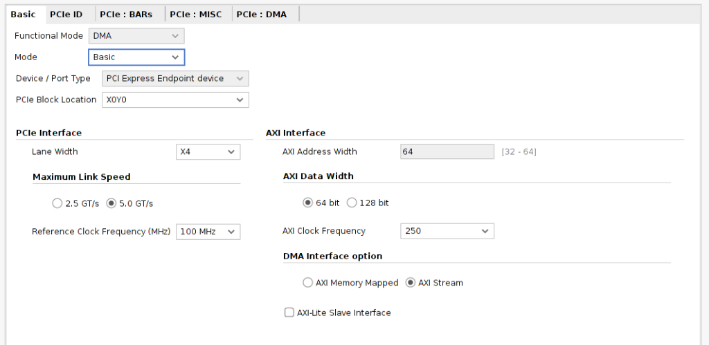
When the drivers are installed and the hardware is detected correctly, we can develop an application to use them. As I mentioned, for this project we will use the Litefury board, which uses the four PCI lanes of the M.2 connector. We have to create a new project, and add the IP DMA/Bridge Subsystem for PCI Express. Since the goal of the project is to connect the PCIe channel to the xFFT IP, we need to change the DMA Interface option to AXI Stream. Maximum link Speed will depend of the part you are using, in this case, the XC7A35T-2TFGG484 can achieve up to 5.0 GT/s. The AXI Clock Frequency will be set to the maximum, 250MHz.
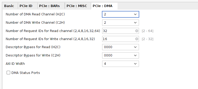
In the DMA tab, we will configure the DMA channels. The xFFT IP needs two AXi Stream channels, for the configuration and the data, therefer the configuration number of Host to Card channels has to be set in two. The configuration channel of the xFFT only write from host to IP, so the number of the Card To Host channels can be configured as one.
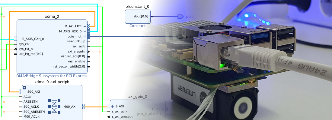
Once the DMA/Bridge Subsystem for PCI Express IP is configured, we can build the rest of the components in the block design. I also added an AXI GPIO to manage the four leds of the board.
The xFFT IP configuration has to allow the minimum latency in the FFT compute. Configuration values I has select are the next.
- Transform length: 1024
- Architecture: Fastest is Pipeline, Streaming I/O
- Target clock frequency: 250 MHz (AXI clock)
- Scaling options: Scaled. We will need to configure the scale factor for each FFT stage through the DMA config channel.
- Output ordering: Bit / Digit reversed order. The output of the FFT will be misordered. It is easy to find the corresponding harmonic value knowing the definition of the FFT. If we select for this field the configuration Natural Order setting, the latency of the xFFT is increased almost twice.
With this configuration, the latency of the xFFT IP is 8.604 us.
Regarding the constraints, Litefury board has connected the PCI Lanes in a different order than xDMA IP expects. As the xDMA IP has its constraints, we need to change the processing order of the xdc files. To do that, we will generate 2 different xdc files, one with the PCIe constraints, and the other one with the generic constraints. For the file that contains the PCIe constraints, we need to change the processing order to Early. We can do that from the user interface or execute the next tcl command.
set_property PROCESSING_ORDER EARLY [get_files /home/pablo/Desktop/pedalos/litefury_early.xdc]
The content of the both xdc files is shown below.
# Early constraints
###################
set_property PACKAGE_PIN J1 [get_ports pcie_rstn]
set_property IOSTANDARD LVCMOS33 [get_ports pcie_rstn]


set_property PACKAGE_PIN G1 [get_ports {pcie_clkreq[0]}]
set_property IOSTANDARD LVCMOS33 [get_ports {pcie_clkreq[0]}]

set_property PACKAGE_PIN F6 [get_ports {pcie_refclk_p[0]}]
set_property PACKAGE_PIN E6 [get_ports {pcie_refclk_n[0]}]

# PCIe lane 0
set_property LOC GTPE2_CHANNEL_X0Y6 [get_cells {accelerator_bd_i/xdma_0/inst/accelerator_bd_xdma_0_1_pcie2_to_pcie3_>
set_property PACKAGE_PIN A10 [get_ports {pcie_mgt_rxn[0]}]
set_property PACKAGE_PIN B10 [get_ports {pcie_mgt_rxp[0]}]
set_property PACKAGE_PIN A6 [get_ports {pcie_mgt_txn[0]}]
set_property PACKAGE_PIN B6 [get_ports {pcie_mgt_txp[0]}]

# PCIe lane 1
set_property LOC GTPE2_CHANNEL_X0Y4 [get_cells {accelerator_bd_i/xdma_0/inst/accelerator_bd_xdma_0_1_pcie2_to_pcie3_>
set_property PACKAGE_PIN A8 [get_ports {pcie_mgt_rxn[1]}]
set_property PACKAGE_PIN B8 [get_ports {pcie_mgt_rxp[1]}]
set_property PACKAGE_PIN A4 [get_ports {pcie_mgt_txn[1]}]
set_property PACKAGE_PIN B4 [get_ports {pcie_mgt_txp[1]}]

# PCIe lane 2
set_property LOC GTPE2_CHANNEL_X0Y5 [get_cells {accelerator_bd_i/xdma_0/inst/accelerator_bd_xdma_0_1_pcie2_to_pcie3_>
set_property PACKAGE_PIN C11 [get_ports {pcie_mgt_rxn[2]}]
set_property PACKAGE_PIN D11 [get_ports {pcie_mgt_rxp[2]}]
set_property PACKAGE_PIN C5 [get_ports {pcie_mgt_txn[2]}]
set_property PACKAGE_PIN D5 [get_ports {pcie_mgt_txp[2]}]

# PCIe lane 3
set_property LOC GTPE2_CHANNEL_X0Y7 [get_cells {accelerator_bd_i/xdma_0/inst/accelerator_bd_xdma_0_1_pcie2_to_pcie3_>
set_property PACKAGE_PIN C9 [get_ports {pcie_mgt_rxn[3]}]
set_property PACKAGE_PIN D9 [get_ports {pcie_mgt_rxp[3]}]
set_property PACKAGE_PIN C7 [get_ports {pcie_mgt_txn[3]}]
set_property PACKAGE_PIN D7 [get_ports {pcie_mgt_txp[3]}]
And the generic constraints.
# Normal constraints

set_property PACKAGE_PIN G3 [get_ports {leds[3]}]
set_property PACKAGE_PIN H3 [get_ports {leds[2]}]
set_property PACKAGE_PIN G4 [get_ports {leds[1]}]
set_property PACKAGE_PIN H4 [get_ports {leds[0]}]
set_property IOSTANDARD LVCMOS33 [get_ports {leds[3]}]
set_property IOSTANDARD LVCMOS33 [get_ports {leds[2]}]
set_property IOSTANDARD LVCMOS33 [get_ports {leds[1]}]
set_property IOSTANDARD LVCMOS33 [get_ports {leds[0]}]
At this point, we can generate the bitstream. The configuration of the PCIe lanes in a different order that xDMA IP expects will cause Vivado reports some critical warnings. We do not care about them because the cause of this critical warning is under control.
In my case, the Litefury board is connected to a computer that I use for tests which I connect remotely. This computer has already the xDMA drivers installed and also Python 3.8 and Jupyter Notebook. In order to redirect the HTTP port that Jupyter will create, we need to access to a remote computer through SSH and redirect the address localhost:8080 of the remote to port 8080 of the host. The way to do that is the next.
~$ ssh -L 8080:localhost:8080 pablo@192.168.1.138
When the SSH connection is established, we can open the Jupyter notebook in the remote computer as sudo. Also, remember to change the port to the redirected in the host.
~$ sudo jupyter-notebook --no-browser --port=8080 --allow-root
If we check the devices detected, we can see the two channels of the DMA that we have configured in the XDMA IP. Channels xdma0_c2h_0 and xdma0_c2h_1, are dedicated to transferring data from card to host, and xdma0_h2c_0 and xdma0_h2c_1 are dedicated to transferring data from host to card.
~$ ls /dev
autofs           i2c-0     loop-control  shm       tty23  tty44  tty8       ttyS27   vcs6           xdma0_events_0
block            i2c-1     mapper        snapshot  tty24  tty45  tty9       ttyS28   vcsa           xdma0_events_1
bsg              i2c-2     mcelog        snd       tty25  tty46  ttyprintk  ttyS29   vcsa1          xdma0_events_10
btrfs-control    i2c-3     mei0          stderr    tty26  tty47  ttyS0      ttyS3    vcsa2          xdma0_events_11
bus              i2c-4     mem           stdin     tty27  tty48  ttyS1      ttyS30   vcsa3          xdma0_events_12
char             initctl   mqueue        stdout    tty28  tty49  ttyS10     ttyS31   vcsa4          xdma0_events_13
console          input     net           tty       tty29  tty5   ttyS11     ttyS4    vcsa5          xdma0_events_14
core             kmsg      null          tty0      tty3   tty50  ttyS12     ttyS5    vcsa6          xdma0_events_15
cpu              kvm       nvram         tty1      tty30  tty51  ttyS13     ttyS6    vcsu           xdma0_events_2
cpu_dma_latency  lightnvm  port          tty10     tty31  tty52  ttyS14     ttyS7    vcsu1          xdma0_events_3
cuse             log       ppp           tty11     tty32  tty53  ttyS15     ttyS8    vcsu2          xdma0_events_4
disk             loop0     psaux         tty12     tty33  tty54  ttyS16     ttyS9    vcsu3          xdma0_events_5
dma_heap         loop1     ptmx          tty13     tty34  tty55  ttyS17     udmabuf  vcsu4          xdma0_events_6
dri              loop10    ptp0          tty14     tty35  tty56  ttyS18     uhid     vcsu5          xdma0_events_7
drm_dp_aux0      loop11    pts           tty15     tty36  tty57  ttyS19     uinput   vcsu6          xdma0_events_8
ecryptfs         loop2     random        tty16     tty37  tty58  ttyS2      urandom  vfio           xdma0_events_9
fd               loop3     rfkill        tty17     tty38  tty59  ttyS20     userio   vga_arbiter    xdma0_h2c_0
full             loop4     rtc           tty18     tty39  tty6   ttyS21     vcs      vhci           xdma0_h2c_1
fuse             loop5     rtc0          tty19     tty4   tty60  ttyS22     vcs1     vhost-net      xdma0_user
gpiochip0        loop6     sda           tty2      tty40  tty61  ttyS23     vcs2     vhost-vsock    xdma0_xvc
hpet             loop7     sda1          tty20     tty41  tty62  ttyS24     vcs3     xdma0_c2h_0    zero
hugepages        loop8     sda2          tty21     tty42  tty63  ttyS25     vcs4     xdma0_c2h_1    zfs
hwrng            loop9     sg0           tty22     tty43  tty7   ttyS26     vcs5     xdma0_control
Also, we can see the xdma0_user channel, which allows access to the Master AXI4 Lite interface, xdma0_control which allows access to the Slave AXI4 Lite interface and xdma0_xvc will allow access to the Xilinx Virtual Cable.
Once inside Python, we need to open connections to the different DMA channels with the os library.
# Open devices for DMA operation
xdma_axis_rd_data = os.open('/dev/xdma0_c2h_0',os.O_RDONLY)
xdma_axis_wr_data = os.open('/dev/xdma0_h2c_0',os.O_WRONLY)

xdma_axis_wr_config = os.open('/dev/xdma0_h2c_1',os.O_WRONLY)
In order to write data in the DMA channels, we have to consider that the AXI interface has a width of 64, and the xFFT IP has an interface of 32 bits, so we will need to convert the corresponding data into 64 bits packets, with the interest data in the low 32 bits. In order to make these conversions, we will import the library struct of python, and convert data to <Q format, that is corresponding with a Little Endian Long variable (8 bytes)
# Write DMA Config channel
config = struct.pack('<Q',11)
os.pwrite(xdma_axis_wr_config,config,0)
The value of the configuration that we will send is a bit set in the position 0 in order to select Forward FFT, and also some additional bits that configure the scaling factor. These values will depend on the value of the input signal and also the width selected.
When the xFFT IP is configured through its Config channel, we can generate the signal using numpy library, and also packaged using the struct library.
# Generate Data channel
nSamples = 1024
angle = np.linspace(0,2*np.pi,nSamples, endpoint=False)
sig = np.cos(2*angle)*100
sig_int = sig.astype(int)+100

# Write DMA data channel
data = struct.pack('<1024Q', *sig_int)
os.pwrite(xdma_axis_wr_data,data,0)
These instructions will be executed immediately, and since always that the device exists, the data will be written. The read operation will be delayed until the xFFT has the output value ready. Therefore we can run the read instruction in Python and when data will be available the instruction will be executed. When data is read, it has to be unpacked, and separated into real and imaginary parts.
# Read DMA data channel
fft_data = os.pread(xdma_axis_rd_data,8192,0)
data_unpack = struct.unpack('<1024Q',fft_data)

# Decode real and imaginary parts.
data_real = []
data_imag = []
for i in data_unpack:
    real_2scompl = _2sComplement(i&0xFFFF,16) / 512
    imag_2scompl = _2sComplement((i>>16) & 0xFFFF,16) / 512
    data_real.append(real_2scompl)
    data_imag.append(imag_2scompl)
If we want to perform an FFT in the computer instead of in the FPGA, the instruction will be the next.
# FFT using PC
fft_data_pc = fft.fft(sig)
Now we have two different methods to perform an FFT. To test the performance of both methods, I have written a code that performs 1024 FFTs using the fft instruction of the scipy package, and the FPGA connected through PCI, and the result was that the scipy instruction is 4 times faster than the execution in the FPGA, does this make sense? Of course!! In order to perform an FFT in the computer, the corresponding data is already in there, so there is no data moving between devices. Also, the computer uses its Floating Point Unit (FPU) to compute the FFT, so there is no data change in the process. In the case of the PCI connected FPGA, for each FFT we need first to package data in a format that the xFFT IP can handle. Then the data has to be sent to the FPGA through PCI, which is a high-speed interface but, we need to consider that Python is executed in an Operating System that will introduce a delay in the data sending according to the number of tasks pending to be executed. When the xFFT IP has computed the result, we need to receive the data and undo the transformations. All of these steps will decrease the performance of the FPGA.
To obtain benefits, many in most cases, with connecting an FPGA through PCI to a computer we need to consider first what kind of algorithm we want to execute. To obtain the highest performance, the algorithm has to be executed mostly in the FPGA, so the transactions that involve computers and overall, the operating system have to be the less as possible. Algorithms that match exactly with this requirement are iterative algorithms where we need to find some value or a combination of values given a reduced amount o data. Examples of these algorithms can be neural network training, where the training set is sent to the FPGA and all the iterative processes to train all the neurons are made in the FPGA. Another application could be cryptocurrency mining, where in the case of Bitcoin or Ethereum, a block is sent, and the FPGA has to compute the HASH of this block many times adding a transaction in order to obtain a valid HASH.
Besides the algorithm itself, the FPGA design used has to be optimized to accept PCI transactions to reduce the changes in the format of the data. In this example, we have used the xFFT IP that is not optimized to handle 64-bit data. In the world of hardware acceleration, the design in the accelerator is known as kernel. In this case, the xFFT IP is the kernel. In the next post of the PCI series, I will develop a customized kernel in order to extract all the potential, and design a real hardware accelerator.


