Developing a SYZYGY peripheral
A few years ago, when I started to hear about SYZYGY, it seems me very useful interface because it is in the middle of PMOD and FPGA Mezzanine Card (FMC). Before that, all high-speed interfaces, even if they use only a few pins, were connected to the carrier board using a high pin density FMC, high as the Low Pin Count variant (LPC) of FMC has 160 IOs. Also, we have PMOD, with only 8 IOs, but regarding the speed, using this interface we “only” can achieve around 20 MHz. Then Opal Kelly realizes that this gap was too big, and developed SYZYGY. If you don’t know this company, they are such important than they have the XEM8320 which is the first, and unique, development board for Artix Ultrascale+. Now, we can find several development boards from many vendors that have included SYZYGY interfaces in their boards like Digilent and AVNET with the new ZUBoard.
SYZYGY has multiple features, but one of the most important is that the voltage of the IO pins is configurable so SYZYGY peripherals can use from 1.2 volts up to 3.3 volts. This configuration has to be stored in some place and this place has to be able to, first, act as an I2C slave, and second, configure its I2C address according to an analog voltage read. These requirements make that a simple EEPROM memory won’t be enough, therefore the only option is to add to the peripheral board a little microcontroller. On this microcontroller will be stored the configuration, which is known as SYZYGY-DNA, and a program that reads the analog voltage and configure its I2C address according to the voltage read.
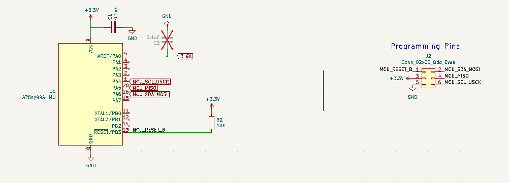
For the peripheral board, as we mentioned before, we need to include in our board a small microcontroller that manages the I2C communication and stores the configuration of the board. The recommended microcontroller is a Microchip ATTiny44A. This is a cheap microcontroller, around 1$, and also is the supported microcontroller in the SYZYGY FPGA ecosystem, so I have used this one on my board. The schematic of the SYZYGY DNA is the next.
You can see that only the microcontroller and a few passive components are needed, so the BOM cost is almost the cost of the IC.
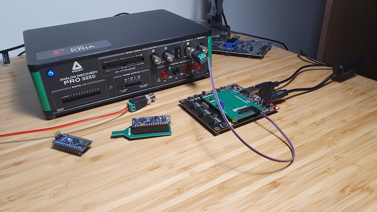
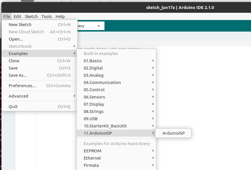
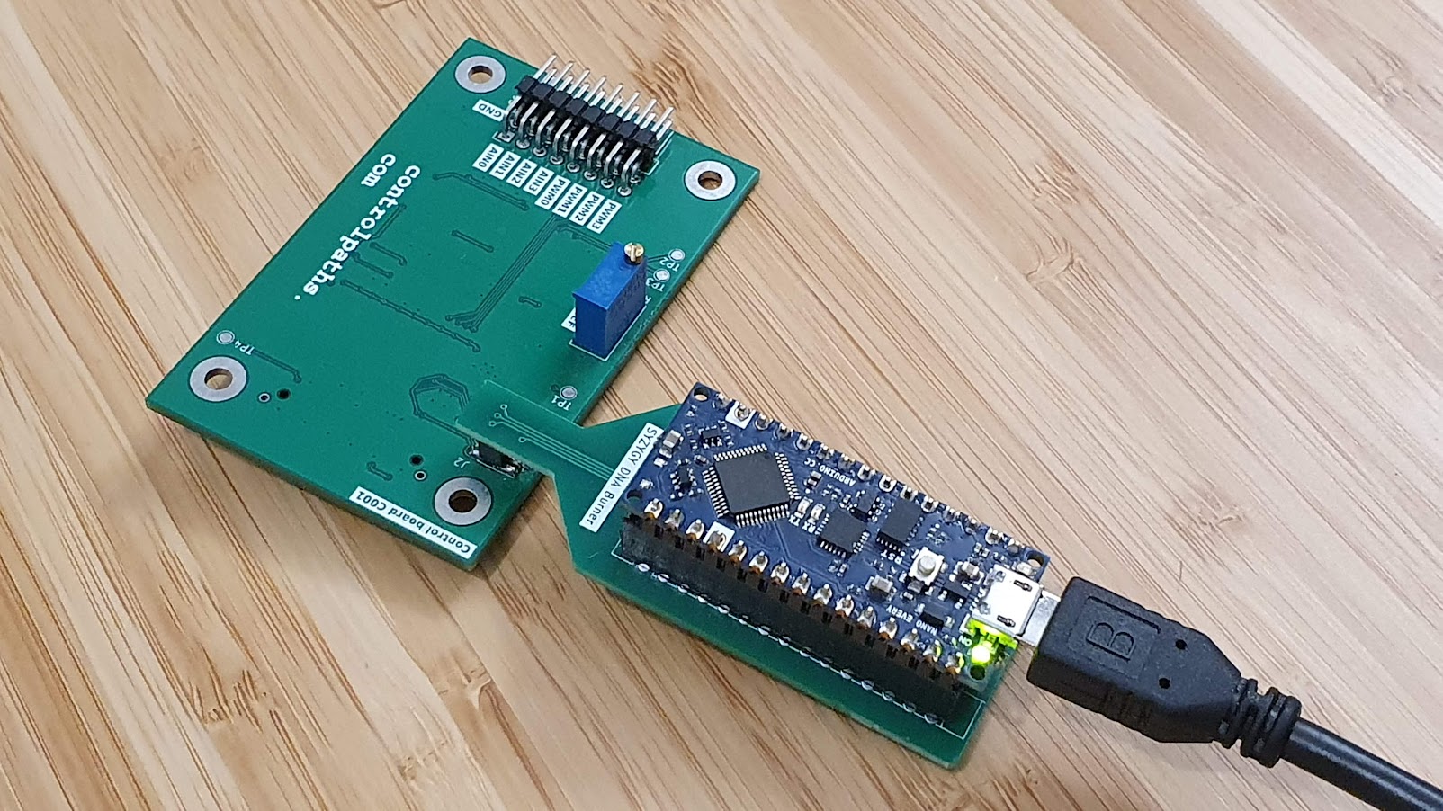
OK, we have the microcontroller, the next is programming that microcontroller. To do this, as if we are using any other microcontroller is to get a programmer and an IDE, but using this microcontroller has many advantages also on this side. Since the Microchip ATTiny comes from ATMEL, we can use an Arduino board as a programmer, so we won’t need a programmer if we have in our lab any Arduino board. In my case, I used an Arduino Nano Every. Then, we can connect the board to the computer, opening the Arduino IDE, and open the example Arduino ISP, which will convert the Arduino Nano Every into an AVRISP programmer.
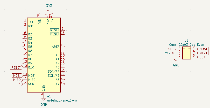
The connection of the Arduino Nano to the SYZYGY DNA IC is quite simple since only the SPI has to be connected. In the next image you can see the schamtic of the board I designed to program the DNA.
Now, its time of the software. To write the firmware of the SYZYGY DNA, we have to use the Python application. First, we need to download the repository SYZYGY-tools from SYZYGY’s GitHub. The repository consists of a set of different folders. The folder where the application we are going to use is located is dna-tools. In this folder, we can find a Python script. In this Python script, we need to make some changes in order to use the programmer Arduino ISP instead of the default programmer. To do this, in the function program we need to change the arguments of the call to avrdude, and add -P /dev/ttyACM0 -c avrisp -b 19200. The modified program function is the next.
def program(firmware_hex_file, eeprom_hex_filename=None):

    # Program the appropriate fuse bits
    program_cmd = "avrdude -pt44 -P /dev/ttyACM0 -c avrisp -b 19200 -u -Uefuse:w:0xFE:m -Uhfuse:w:0xDD:m -Ulfuse:w:0xE2:m"

    program_return = subprocess.call(program_cmd, shell=True)

    if program_return != 0:
        print("Error Setting Fuse Bits")
        exit(1)
    else:
        # Load the firmware and DNA
        program_cmd = f"avrdude -p t44 -P /dev/ttyACM0 -c avrisp -b 19200 -B1 -Ueeprom:w:{eeprom_hex_filename}:i"

        program_return = subprocess.call(program_cmd, shell=True)

        if program_return != 0:
            print("Error Programming Flash")
            exit(1)
        else:

            if eeprom_hex_filename:
                # Load the EEPROM power sequence data
                program_cmd = f"avrdude -p t44 -P /dev/ttyACM0 -c avrisp -b 19200 -B1 -Ueeprom:w:{eeprom_hex_filename}:i"
                program_return = subprocess.call(program_cmd, shell=True)

                if program_return != 0:
                    print("Error Programming EEPROM")
                    exit(1)
Now, to configure the content of the SYZYGY DNA, we need to create a JSON file. Examples of the content of the JSON file can be found in the folder syzygy-tools/szg-dna/. For the board I have developed, I need VIO set to 1.8V, to make it compatible with boards based on Zynq MPSOC, like the ZUBoard. Also, we can define the maximum load of the power supplies. Finally, we can configure a manufacturer name and some other fields.
{
	"max_5v_load":   200,
	"max_3v3_load":  10,
	"max_vio_load":  20,
	"is_lvds":       false,
	"is_doublewide": false,
	"is_txr4":       false,
	"vio": [
		{ "min": 180, "max": 180 },
		{ "min": 0,   "max": 0 },
		{ "min": 0,   "max": 0 },
		{ "min": 0,   "max": 0 }
		],
	"manufacturer_name": "Controlpaths",
	"product_name":      "SZG-IO001",
	"product_model":     "SZG-IO001",
	"product_version":   "A"
}
Besides the JSON file, which will be sent to the SYZYGY DNA IC, we also need to program this IC with valid firmware. This firmware can be downloaded also from SYZYGY’s GitHub, this time from the repository avr-dna-fw. This repository contains the files needed to compile the firmware, but not the firmware itself. After installing avrgcc, we can compile and generate the hex file following the next instructions.
pablo@friday:~/git$ git clone https://github.com/SYZYGYfpga/avr-dna-fw.git
pablo@friday:~/git$ cd dna-firmware
pablo@friday:~/git/dna-firmware$ mkdir avr-dna-fw-build
pablo@friday:~/git/dna-firmware$ cd avr-dna-fw-build
pablo@friday:~/git/dna-firmware/avr-dna-fw-build$ cmake ../avr-dna-fw
pablo@friday:~/git/dna-firmware/avr-dna-fw-build$ make
Once we have the JSON file, and the firmware for the ATTiny44a, we can connect the boards and execute the script syzygy-tools.py
pablo@friday:~/git/syzygy-tools/dna-tools$ python ./syzygy-tools.py -d szg-cp-std.json -f ./avr-dna-fw.hex
DNA: szg-cp-std.json
Serial Prefix: 2324000
Scan serial label barcode or type serial to complete the full serial value (value is case insensitive. q to exit)
SERIAL: 2324000
DNA Serial: 2324000
SYZYGY DNA Data:
4E 00 28 00 01 01 00 00 C8 00 0A 00 14 00 00 00
B4 00 B4 00 00 00 00 00 00 00 00 00 00 00 00 00
0C 09 09 01 07 00 8D 6E 43 6F 6E 74 72 6F 6C 70
61 74 68 73 53 5A 47 2D 49 4F 30 30 31 53 5A 47
2D 49 4F 30 30 31 41 32 33 32 34 30 30 30
No Power Sequence Data Found

avrdude: AVR device initialized and ready to accept instructions

Reading | ################################################## | 100% 0.02s

avrdude: Device signature = 0x1e9207 (probably t44)
avrdude: reading input file "0xFE"
avrdude: writing efuse (1 bytes):

Writing | ################################################## | 100% 0.01s

avrdude: 1 bytes of efuse written
avrdude: verifying efuse memory against 0xFE:
avrdude: load data efuse data from input file 0xFE:
avrdude: input file 0xFE contains 1 bytes
avrdude: reading on-chip efuse data:

Reading | ################################################## | 100% 0.01s

avrdude: verifying ...
avrdude: 1 bytes of efuse verified
avrdude: reading input file "0xDD"
avrdude: writing hfuse (1 bytes):

Writing | ################################################## | 100% 0.01s

avrdude: 1 bytes of hfuse written
avrdude: verifying hfuse memory against 0xDD:
avrdude: load data hfuse data from input file 0xDD:
avrdude: input file 0xDD contains 1 bytes
avrdude: reading on-chip hfuse data:

Reading | ################################################## | 100% 0.01s

avrdude: verifying ...
avrdude: 1 bytes of hfuse verified
avrdude: reading input file "0xE2"
avrdude: writing lfuse (1 bytes):

Writing | ################################################## | 100% 0.01s

avrdude: 1 bytes of lfuse written
avrdude: verifying lfuse memory against 0xE2:
avrdude: load data lfuse data from input file 0xE2:
avrdude: input file 0xE2 contains 1 bytes
avrdude: reading on-chip lfuse data:

Reading | ################################################## | 100% 0.01s

avrdude: verifying ...
avrdude: 1 bytes of lfuse verified

avrdude done.  Thank you.


avrdude: AVR device initialized and ready to accept instructions

Reading | ################################################## | 100% 0.03s

avrdude: Device signature = 0x1e9207 (probably t44)
avrdude: erasing chip
avrdude: reading input file "fw_temp.hex"
avrdude: writing flash (3150 bytes):

Writing | ################################################## | 100% 5.35s

avrdude: 3150 bytes of flash written
avrdude: verifying flash memory against fw_temp.hex:
avrdude: load data flash data from input file fw_temp.hex:
avrdude: input file fw_temp.hex contains 3150 bytes
avrdude: reading on-chip flash data:

Reading | ################################################## | 100% 2.74s

avrdude: verifying ...
avrdude: 3150 bytes of flash verified

avrdude: safemode: Fuses OK (E:FE, H:DD, L:E2)

avrdude done.  Thank you.

DONE
Now, if we connect the SYZYGY peripheral to a SYZYGY Compatible board, we will see how, first, the led of the VIO enabled is turned ON, and then, the VIO is set to a correct value. Remember that the ZUBoard does not read the SYZYGY DNA to set the VIO, it is configured by HW.
Developing SYZYGY peripherals is not a very easy task, especially if you want to develop your board using home methods, but if you are comfortable with Kicad, you can easily develop a SYZYGY peripheral using the SYZYGY templates that you can find in GitHub. Then, by sending the board to a cheap PCB manufacturer like PCBWAY you can create your peripheral. The final step is soldering. Here, you can use a stencil and an iron to solder your board, or if you are very handy, you can use a stencil and a solder, it’s completely up to you. The key is that we can use high-speed peripherals using an small interface, which also makes that the cost of the SYZYGY boards won’t be so expensive.


