Implementing high order filters with FIR Compiler.
Many times, in our designs we find a signal that our interest band of frequency is very close to the band that we need to reject. In this case, in general, the most efficient way to attenuate the unwanted signal is using a 4th or 6th order IIR filter. This method will work very well, however, as we see in this post, the shape of the signal will be distorted due to the non-linear phase of this filters. Situations, where the signal of interest is very close to the other unwanted signals, is very common in audio processing, where we can find equalizers that split the audio band (20Hz-20kHz) in 32 independent bands. That means very narrow filters in order to control the amplitude of each of the bands without interfering with the other bands. For this kind of application, we cannot use IIR filters due to the distortion that they will add to the signal, so in these cases, we need to use FIR filters.
FIR filters have, for the same order, a soft transition band than the IIR filters. Due to this, for the same attenuation, is very common to need high-order FIR filters in our designs. Designing and implementing a 8th or 32th order FIR filter is easy. We only need a pipeline with n states, and then we need to multiply each register output by its corresponding coefficient. Also, we can design symmetric filters and then save half of the multiplications by adding the output of the register N to the order-N.

In this post we are going to use the tool ASN Filter Designer from Advanced Solutions Netherlands, to design the FIR filter and generate the coefficients (.coe) to use in the FIR Compiler IP from Xilinx. We already use this IP in this post. To test everything I have designed a simple AXI 4 Stream IPs for the ZMOD DAC and ZMOD ADC from Digilent.
First, we are going to design the filter. This time we will use this tool to design a FIR filter with a sample rate of 10Msps. The pass band of the filter goes from DC to 1Mhz, and the stop band starts at 2MHz, with an attenuation of 80dB. Due to the short transition band and the high attenuation, the order of the filter calculated if 47. I have configured Parks-McClellan as the method to compute the coefficients and the order, but there are several methods that the application allows to select.

Once the filter is designed, we need to quantify the coefficients. For this project, I will use the format I1Q15. Notice that the integer part of the coefficients is always zero with this format, so if you change the characteristics of the filter, check the values of the coefficients before selecting the format. We can see on the bottom-right of the application window both the real and quantized positions of the zeroes.

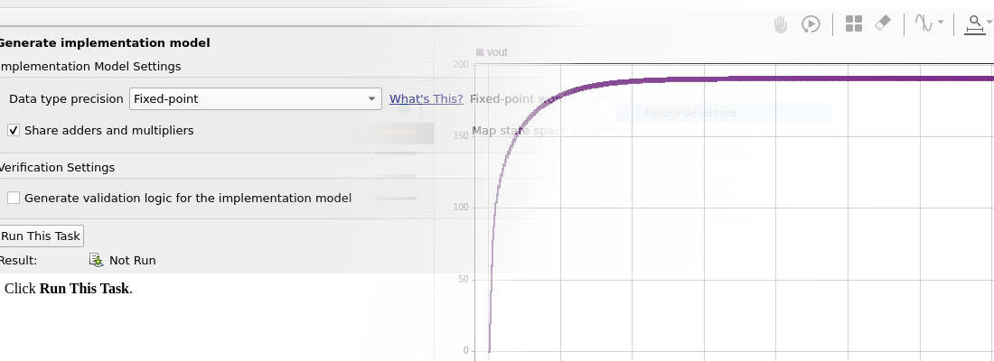
Inside the application, we can test this filter with a generated signal. This time I generated a 1Mhz signal with a 2Mhz harmonic of the same amplitude, and we can see how the output contains only the 1MHz signal.

Once we have our filter tested, the application allow us to create the coe file automatically. To do this you have to click over H(s) symbol, and then select Xilinx FIR Compiler. Now you can save this file.

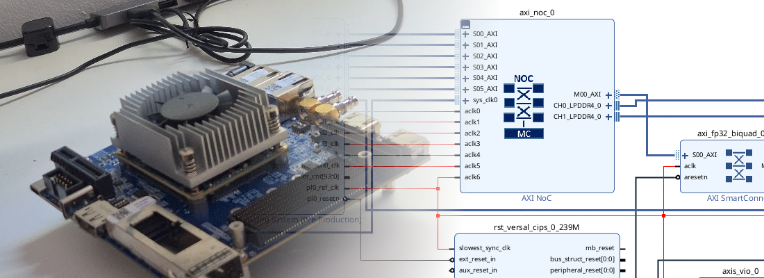
The figure below shows the block design I have used in Vivado. The signal is read by the IP axis_zmod_adc. ZMOD ADC is clocked at 100MHz, so it returns us a sample rate of 100Msps. As the filter we designed has a sample rate of 10Msps, we need to decimate the input of our filter.

To perform the decimation, I have designed the axis_decimator hdl code, which decimates the input signal by the rate configured in the parameter. The output of the axis_zmod includes the value of both channels package in a 32 bits word. This format is the same that the axis_decimator input and output.

The next block is the FIR Compiler. The filter we are going to use is a single rate filter, with only one coefficient set sourced by a .coe file. The filter we have designed is symmetrical, so in the Implementation tab, we can configure the filter as Symmetrical to reduce the number of DSP slices used. As the ADC and the DAC have both 2 channels, the FIR filter designed will have also 2 channels. We can configure the FIR Compiler IP to integrate 2 independent channels that share the coefficients set. We can do this in the Channel Specification tab, modifying the parameter Number of Paths to 2.

The output of the filter has a width of 64, so we need to return the width to 32 bits (16 + 16). we can do this using 2 Slices IP to extract the 16 bits MSB of each half of the axis_tdata wire, and then concatenate the output.
[ ]Finally, this output is connected to the axis_zmod_dac to extract the signal.
The clock used by the IDDR primitive of the axis_zmod_adc is connected to a BUFG through the IP Utility Buffer. This ensures that the clock signal is routed through the clock paths in the FPGA. The next images show the response of the filter when the input is a signal of 100kHz, which is in the pass band, and also the response of the filter when we apply the same signal that we used to simulate the filter, a 1MHz sine added to a 2MHz sine. We can see also the effect of the decimation.

Many times, some partners say me that FPGA has larger development times, well, by combining different tools like FIR Compiler and ASN Filter designer allows the engineers to develop in less than an hour (yes! less than an hour), a filtering system. This is great because let the designer test different options, make mistakes, and get the best solution. Obviously, this cannot be done if we don’t have a collection of verilog files tested and ready to use. Is the case of the axis_decimation, or axis_zmod_adc and axis_zmod_dac. but once you have your collection of the most used files, you can develop really fast your prototype designs. Thanks for reading!
All the files are available to download in Github.