Equalizing IIR filters for a constant group delay.
In the previous post, I designed an audio equalizer. In that design, I used 3 different FIR filters to split 3 different frequency bands in order to send them to different speakers. Very low frequencies will be sent to the sub-woofer, medium frequencies to the woofer, and high frequencies to the tweeter. FIR filters are a good option to perform this kind of processing since, having their symmetric coefficients, they delay all the frequencies the same amount of time, N/2, so if we use 3 FIR filters with the same number of taps, all the frequencies of our system will have the same delay, that means that our system will be a delayed linear system (the input frequencies are present in the output signal at every moment), I other words, the out filter has linear phase. On the other side, in order to achieve high attenuation slopes, we need high-order FIR filters. Is common in signal processors the capability to implement high-order FIR filters, for example, the Analog Devices SHARC processors can implement up to 1024th-order FIR filters. To achieve the desired attenuation with a lower-order filter we can use IIR filters instead of FIR.
IIR filters have the advantage that we can achieve high attenuation with a significantly lower order than FIR filters. As we have seen in this post, this kind of filter has poles and zeroes, so they can be unstable in certain cases. In this post, we won’t focus on the stability, since we assume that the filter and its quantification are stable, but in its group delay. The group delay can be described as the delay for each frequency, knowing that a signal is an addition of several sinus signals with different frequencies. When we are working with FIR filters, all sinusoidal components of the signal spend the same amount of time to pass through the filter, this makes the mix of frequencies at every moment will be the same at the input and the delayed output, the system is linear. In the case of IIR filters, this characteristic is not fulfilled, so if our signal information is composed of several frequencies, the use of this kind of filter will be discouraged. There are several cases where the information is composed of different frequencies, one of them is the communications lines, where we can have different bands on the same channel and we need synchronism between them. Another case is when we are processing audio signals, where a sound produced by different instruments has different frequencies, but we need to listen to all of them at the same time. In order to make that possible, we can use FIR filters, or we can use equalized IIR filters, to achieve linear phase at least in the pass band, using all-pass filters.

If we see the frequency response of an all-pass filter, we will see a constant magnitude of 0 dB in all frequencies, and a phase that goes from 0 to 2pi. This kind of filter is used to change the phase of a signal keeping its amplitude. As we said in the previous post, the group delay is the derive of the phase, so if we can change the phase of the signal, we can change its group delay, and in some cases, configuring this all-pass filters correctly, we can achieve systems that have linear phase. To do this, we are going to create a chain of biquad filters, where some of them are in charge to filter and change the magnitude of the signal, and others will correct the phase delay. For this example, we will design a pass-band filter to the band from 4 to 8 kHz.

Configuring the all-pass filter to obtain a linear phase in the pass band can be very tedious, so for this post, I will use the tool Filter designer tool from the company Advanced Solutions Nederland B.V. that allows doing this configuration graphically.
In order to continue with the previous post, we will redesign the medium frequency band, this time using an IIR filter. As this filter can achieve greater attenuation than low-order FIR filters, we will define our filter as a band-pass filter a little bit more restrictive, with a pass band from 500hz to 5kHz, and an attenuation of at least 27 dB at 200 Hz and 8kHz.
First, we need to configure the band-pass filter. We can do this by entering the frequency values on the table, or by moving the points in the bode diagram. The configuration of the filter is the next.

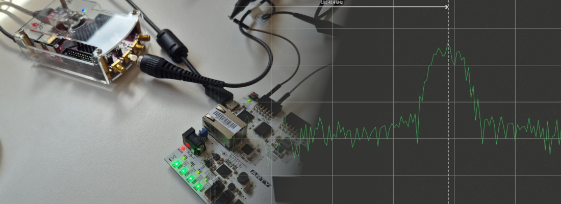
On the left of the window, we can see the position of the filter’s poles and zeroes. At this point, we can see how the group delay on the pass band between around 40 and 5 samples. To verify the response of the filter, we can do it inside the application by opening the built-in signal analyzer. The signal we will use to verify the response will contain 2 harmonics in 2 kHz and 4 kHz. We can see the response in the next figure.

We will notice that the shape of the output signal has changed with respect to the input signal. This effect is due to the different delay that each signal experiment.
To improve this response, we need to configure the all-pass filters, To do this, there are several methods based on mathematics, and also come methods based on machine learning. In this example, we will use a powerful feature of this software. On the top of the window, we can click over the 3 points to enable the addition of all-pass filters biquad to our system.

Now on the bode diagram, we can add points that are corresponding with pole-zeroes pairs of all-pass biquad filters, which will change the phase of the filter. In this case, I have added 3 pairs, that are corresponding with 3 biquads, and the group delay variation will decrease significantly in the pass band. On the other side, the global delay has been increased due to the addition of 3 more stages to the filter.

The order of the final system will be the order of the initial passband filter added to 2 times the number of biquads added for the equalization.

In the new response, we can see that the signal is inverted with respect to the input, but if we focus on the shape of the signal, we will see that is very similar to the input signal. That means that the components of the signal are the same at every moment. With the help of MATLAB we can apply an inversion to the signal, and also correct the phase delay to verify the correct behavior.

These corrections can be done offline, but when we use this kind of filter within an audio system, the shape of the signal is the only one that matters to produce the corresponding sound.
Regarding the implementation in the FPGA, we have to add to the block design both I2S transmitter and receiver, Slice and Concat blocks to match the widths and the 8 biquads, 5 for the band-pass filter and 3 for the all-pass filter. In order to make easiest the introduction of the coefficients, I have generated a new biquad module where the coefficients are parameters, and the multiplications are registered `axis_biquad_v1_1.v^.

Complete block design is shown in the next image, with the biquads grouped in 2 hierarchy blocks.

Regarding the resources used, for 20-bit width coefficients and 24-bit width for the input and output, the amount of DSP blocks used is 66, that is a high number for only equalize one band.

The use of the high amount of DSP Slices unregistered in series has other problems. DSPs are located in some place of the FPGA, more precisely in columns. If we want to use a lot of them and connect them in series, we will generate a very long path between the input of the first DSP Slice and the output of the last DSP Slice, which will report timing errors. To avoid that we need to register the outputs of the DSP Slices, and notice that an extra delay will be added.

As point, we have seen how we can correct the group delay of a filter by adding all-pass biquads to the system. For some systems where synchronization is critical, like communication systems, we have no choice, and we have to use linear systems, but the goal of this post is to design an audio system. If we analyze the variation of the group delay in the pass band of the non-equalized filter, we can see a delta of 40 samples between the fastest frequency to the slowest. In a system with a sampling frequency of 44 ksps, these 40 samples represent less than 1cms of delay. On the other side, regarding the implementation, increasing the number of biquads, also increase the number of resources used in the FPGA. So, need we to make the filters linear in audio systems? As always, it depends, but in general, delays of 1 ms in audio frequencies can be acceptable, even delays of 10 ms for the lower frequencies can be acceptable without quality loss.