Using Xilinx’s FIR Compiler.
When we need a FIR filter, in general, or at least in my case, we already have a FIR filter HDL, where we only need to change the filter order to the application needs, in most cases this configuration can be parametrized, and the second thing we have to do is compute, quantify and write this new coefficients on our HDL, and, if there are not problems with the width of the internal operations, the FIR filter is complete. But in other cases, we have not a FIR filter HDL, or we cannot use the filter that we already have. Even though Vivado is not a signal processing application, that is obvious, it has an interesting tool that can be helpful in most cases, the FIR Compiler.
FIR compiler is not a filter compute tool, at least not for all steps, but it quantifies, and is in charge of select the correct widths to the operations, and this could be enough to users that take care only to the coefficients calculation if you are not familiar with this other terms.
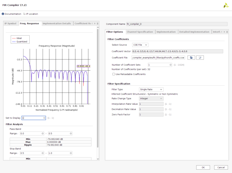
The coefficients can be passed to the tool through a coefficient vector wrote directly on the IP configuration, or though a .coe file, that for me, is the best choice for avoid mistakes, since the .coe file can be automatized with a python script. Once the .coe file is read, tool show us the filter response. On Implementation tab we can configure the width of this coefficients, and the filter response will be updated to show the quantified response of the filter. Also there is a field on this tab where we can configure if the coefficient set is Symmetric, Not symmetric, or let Vivado select the correct choice. This configuration will impact directly to the DSP Slices used, because in case of symmetric coefficients, and a clock frequency at least twice of the sample frequency, a single multiplier will be used for 2 same coefficients.
Sampling frequency and clock frequency can be configured on Channel Specification tab. This 2 frequencies will also impact to the DSP Slices use because tool will detect how many clock cycles has to perform the multiplications, for example, for a 400MHz clock frequency, and 100MHz sampling frequency, for each sample, we will have 4 clock cycles, so we can perform up to 4 multiplications, and therefore, the number of DSP Slices can be 4 times lower. Because of that, we have to take care to fill all the multiplication steps. That is, if we have a clock frequency of 500MHz and a sampling frequency of 100MHZ with a 32 coefficients filter, to perform each multiplication we have 5 clock cycles, so as we have 32 coefficients, 6 multiplicators will perform 5 operations, and the other one will perform only 2. This may cause that the output of the filter between samples can be incorrect. To avoid that, we have to think that the FPGA will use 6 multiplicators, so the resources used to compute a 32 coefficients will be the same of computing 36, so maybe it could be interesting to improve the filter response to increase the number of taps.
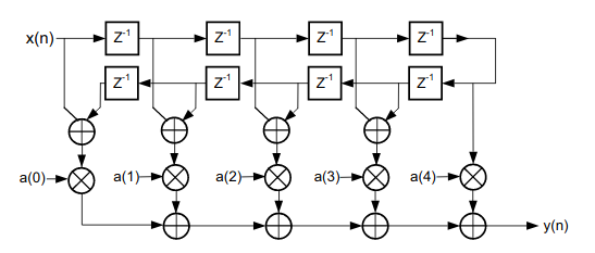
Regarding the filter architecture it will depend on the symmetry or asymmetry of the coefficients. In case that we had select inferred regarding the coefficients symmetry, Vivado will select also the best choice on the filter architecture.
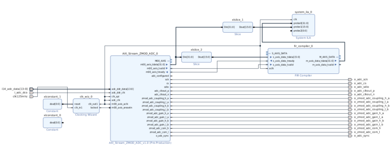
To test this tool, I have created a simple design where I have a Digilent’s ZMOD ADC AXI-Stream IP, and a FIR Compiler filter. This time, instead of check the output signal on the Scope, I have used an ILA to test the filter and check the output.
Slice IPs are need because the AXI-Stream output of the IP has 32 bits width and contains 2 channels information, so we need to extract only the bits 32:16. Input signal is generated with a signal generator, and is connected to the ZMOD ADC.
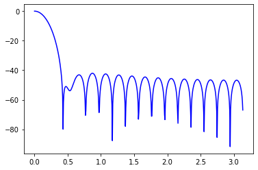
Filter designed if a 32th order FIR filter with a cutoff frequency of 0.01. That means for a 100 Msps, a cutoff frequency of 500kHz.Slice IPs are need because the AXI-Stream output of the IP has 32 bits width and contains 2 channels information, so we need to extract only the bits 32:16. Input signal is generated with a signal generator, and is connected to the ZMOD ADC.
Filter designed if a 32th order FIR filter with a cutoff frequency of 0.01. That means for a 100 Msps, a cutoff frequency of 500kHz.
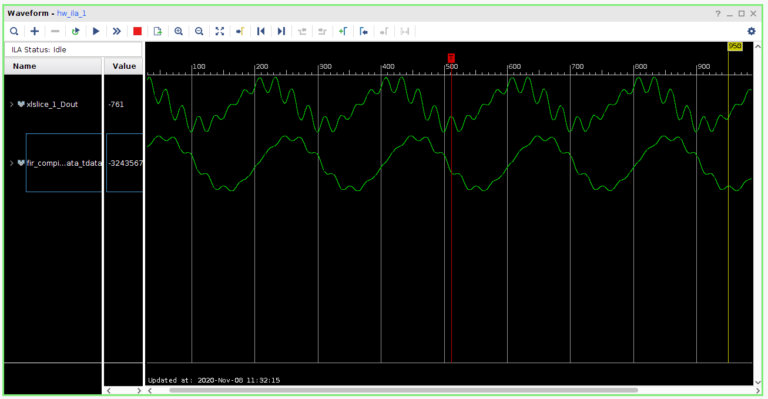
The output of the ILA is shown on the next image.
The input signal is a 500kHz sine with a 7th and 8th harmonics. And the bottom signal if the filter output.
FIR compiler is an interesting tool since you can develop a FIR filter in minutes, since you only has to compute the coefficients, and the tool will implement the filter for you.


