Controlling a SMPS from MSS with SmartFusion2 SoC.
FPGAs have been present in the telecommunications field for many years, almost since they were created. On the other side, there are fields where FPGAs have not arrived yet for several reasons such as power consumption or price. But there are other groups where FPGAs have not been present for many years, and industrial is one of these fields. Manufacturers like Microchip or Xilinx have FPGAs focused on this market segment. Nowadays, it is very common for manufacturers to show us industrial applications where the brain of the system is an FPGA or an SoC. In this post, we will see how by using Microchip Technology’s Libero® SoC 2021.2 design suite and SmartFusion2 SoC we can control a buck power supply.
Buck is the topology of a switched mode power supply (SMPS), a type of power supply that works by making the transistors work in their saturation zone, i.e. the transistors act as a switch allowing and stopping the passage of current. A filter is usually connected to this switching cell to smooth the voltage and current that will later be supplied to the load. In case the load is a motor, it acts as a filter. Here you can find a detailed explanation from Microchip of how this supply works.
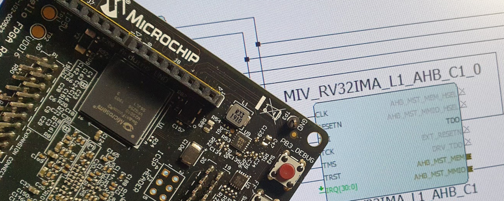
To control this power supply, we will generate a PWM signal where the duty cycle will be proportional to the difference between the output voltage and the reference voltage. This control will be implemented in the Trenz SMF2000 board, which is based on Microchip’s SmartFusion2 SoC. This SoC has inside an FPGA and a microcontroller subsystem (MSS) that is an Arm® Cortex®-M3 core that can run up to 143 MHz.
At this point, we need to ask ourselves what will be implemented in the MSS and what in the FPGA. There is no right or bad answer because this decision must be based on the application itself. In this case, I would like to show you how we can use both devices using the resources that Libero SoC software and the Arm ecosystem provide us The solution I will present you implements the acquisition in the FPGA while the control is performed by the Arm Cortex-M3 MSS.
When we talk of acquisition, we usually talk about the analog-to-digital converter and also the filtering of the signal we are going to read. In this blog, we have seen in many posts how we can perform these two tasks in an FPGA easily. Also, the board I have designed with the buck power supply uses instead of ADCs, delta-sigma modulators, that need a sinc3 filter to transform the binary stream into a digital word. Fortunately, Libero design suite has in their catalog a group of IP for motor control, and a sinc3 filter is included.

On the other side, to perform the control, we also can use the FPGA, since the motor control catalog also includes a Proportional – Integral control IP, but I decided to use the MSS since we can develop ourselves or find the code to perform a PI control in the CMSIS repository . The output of the controller must be applied to the duty cycle of the PWM, so the easy way is to also use the MSS to generate the PWM signal. In this case, we will use the corePWM peripheral.
At this point, we have the acquisition in the FPGA, and both the controller and the actuator in the MSS, so the next thing is to communicate both to write to the controller the output voltage that allows it to calculate the control action. For this task, we need to create an HDL that sends the value of the voltage from the FPGA to the MSS through APB3 interface.
The entire design will look like the next image.

First of all, we will create a new project for the SMF2000 board based on an MSS design. Now, when the system builder is opened, we select as memory the eNVM, selecting a width of 64k, and we will leave it empty for the moment.

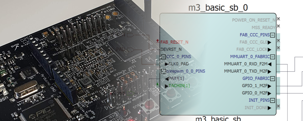
In the peripherals tab, we are going to deselect all the MSS peripherals except the MM_UART_0, and we will add CorePWM to the fabric interconnect (FIC_0) and an AMBA Slave. The CorePWM will be used to generate the PWM signal, and also we need to add a fabric AMBA Slave, that will be used to communicate the FPGA with the MSS.

In the configuration of the CorePWM we need to make some changes. First, we will select only one channel, and then we need to uncheck the options Fixed Prescale and Fixed Period. These modifications will allow us to configure the PWM frequency up to 16 bits since the data bus is 8 bits.

Now, in the configuration of the fabric AMBA Slave, we need to select as Interface Type APB3.

Now with these two peripherals configured, the next is to configure the clock. This time we will use the internal oscillator of 50MHz, and the M3 clock configured to 100MHz. This will be important to configure the PWM frequency later.
The rest of the tabs in the configuration wizard will remain with their default configuration.
Now we will add the sinc3 filters. The board I have designed, besides the output voltage measure, also has measures for the input voltage, and the input and output currents, so we will need four sinc3 filters in our design.
In the configuration of the sinc3 filters, we need to define the decimation factor, which is the inverse of the oversampling ratio. The modulator I have used works with a clock of 10MHz, so a decimation factor of 2^9 results in an acquisition frequency of 19 kHz. The width of the output word is configured at 16 bits (this width is related to the SNR of the modulator and the order of the sinc filter). The modulator I have used is bipolar and the output is not negated (1 means not negated).

Finally, we need to develop the HDL to send the 4 measurement values to the MSS through APB3 interface. In order to develop the hdl, I have based on this document from Microchip. This document explains where the read_enable signal is set and when the write enables signal is set.
The input and output signals for the APB3 interface are the next.
/* apb3 interface */
input [7:0] paddr, /* register address */
input penable, /* enable peripheral bit */
input psel, /* selected peripheral bit */
input pwrite, /* write enable */
input [7:0] pwdata, /* data register to write */
output reg [7:0] prdata, /* data register to read */
From these signals, we can extract where the MSS performs a read, and when it performs a write.
assign wr_enable = penable & psel & pwrite;
assign rd_enable = psel & !pwrite;
Now with these 2 signals, and since this code also has to send data from FPGA to the MSS, only read performs will be considered.
/* read logic */
always @(*)
  if (!presetn)
    prdata <= 8'd0;
  else
    if (rd_enable)
      case (paddr)
        input_current_add: begin
          prdata <= input_current[15-:8];
        end
        input_voltage_add: begin
          prdata <= input_voltage[15-:8];
        end
        output_current_add: begin
          prdata <= output_current[15-:8];
        end
        output_voltage_add: begin
          prdata <= output_voltage[15-:8];
        end
        default: begin
          prdata <= 8'd0;
       end
     endcase
Once the code is created, we need to import the file from the Libero project, in the Design hierarchy tab, we have to select the file, and select Create Core from HDL.

Now, click on Yes to add a bus interface. In the newly opened window, we must click over Add Bus Interface… and select the interface APB AMBA2 Slave. Now connect the HDL pins to the corresponding interface pin, and click Apply and Close.

The next step is to drag the new core created to the smart design. Now we have in the canvas all the modules that we will need to connect. The entire design and all the connections are shown in the next figure. Notice that the input reset_I of the sinc3 filters is connected to an active low reset, and the input reg_rst_I is connected to the active high reset.

In the design, I also added a module that split the high eight bits of the input voltage conversion and the output is connected to the eight LEDs of the board. Also, you can see two outputs that are connected directly to the ground. These outputs are the low-side transistor, which is not used in this configuration, and the PWM disable input of the gate driver.
When the design is all connected and configured, we can synthesize the design, and add the constraints file according to SMF2000 pinout and the SMF2000 buck board schematic.
When all the design is implemented, we can program the board and open the Softconsole in order to develop the code that will run in the Cortex M3 processor. Before, from the Firmware Catalog, we will generate the drivers for the corePWM peripheral, and also the example SF2_pwm_slowblink.
Once the example is generated and imported to the SoftConsole workspace, we need to change the main function. First, we will change the Period and the Prescale definition
#define PWM_PRESCALE    20
#define PWM_PERIOD      200
These two definitions will set the PWM frequency in 100e6/20/200 = 25khz, and the PWM resolution will be 1/PWM_PERIOD = 0.5%. Now, in order to read the different measures, we can use the macro HW_gen_8bit_reg(), which returns the 8-bit value of the corresponding address. The address of the APB3 peripheral created can be found in the Address map of the Libero IDE smart design. In this case, the base address for the buck_logic_apb3 is 0x50001000.
input_current_int = HW_get_8bit_reg(0x50001000);
input_voltage_int = HW_get_8bit_reg(0x50001004);
output_current_int = HW_get_8bit_reg(0x50001008);
output_voltage_int = HW_get_8bit_reg(0x5000100c);
Finally, to write the PWM duty cycle, we will use the macro PWM_set_duty_cycle.
PWM_set_duty_cycle( &the_pwm, PWM_1, duty_cycle );
For the control of the output voltage, the regulator I have chosen is a proportional regulator, where the difference between the output voltage and the reference is multiplied by a gain, and the result is applied to the PWM duty cycle.
/* compute error */
error_int = reference_int - output_voltage_int;

/* apply proportional gain */
duty_cycle = error_int * gain;

/* apply saturation */
if (duty_cycle > 250)
   duty_cycle = 250;

if (duty_cycle < 0)
  duty_cycle = 0;

/* write duty cycle */
PWM_set_duty_cycle( &the_pwm, PWM_1, duty_cycle );
With this code, you will be able to control the output voltage by writing the reference in the value that you need at the output of the power supply. Using a proportional gain, the exact value of the output is not guaranteed. The next scope capture shows the response of the regulator for a reference of 10 volts and a proportional gain of 5. The error in the output voltage is 2.6 volts.

in the next capture, the proportional gain is increased to 15, and the error is reduced to 560mV.

Notice that the increment in the proportional gain also causes an increment in the overshoot. In the second capture, we can see how the initial overshoot is greater than the reference.
To perform a control with an exact output value, we will need to add a pole in the regulator, in this case, we will need to use a Proportional – Integral control. The integral side of the regulator will add the error in every control cycle, and then applying a gain to this addition we will ensure an error of 0. The code to add the integral branch in the controller is the next.
/* compute error */
error_int = reference_int - output_voltage_int;

/* proportional gain */
proportional = error_int * gain_p;

/* integral gain */
error_i = error * gain_i;
integral = accumulator + error_i;

/* Addition of both gains */
duty_cycle = proportional + integral;

/* apply saturation */
if (duty_cycle > 250)
   duty_cycle = 250;

if (duty_cycle < 0)
  duty_cycle = 0;

/* write duty cycle */
PWM_set_duty_cycle( &the_pwm, PWM_1, duty_cycle );
Notice that the integral must be selected taking into account the frequency at which the regulator is computed. The next capture shows the response of the regulator with a proportional gain of 2 and an integral gain of 0.1.

The initial overshoot caused by a higher proportional has reduced and the error in the output voltage is 280 mV. Increasing the proportional gain to 5 and the integral gain to 0.2, the output voltage is exactly the reference. In this case, you can see a capture of the voltage captured by the SmartFusion2 SoC.

In this project, we have seen how we can split the control of an industrial system in a SmartFusion2 SoC between the MSS and the FPGA. This is only one way to do this, because, as I said before, for each application we will consider many variables to help us to choose the most appropriate configuration. Proportional – Integral control is widely used in industry, so this example shows an example of a system that you can find in many devices like variable speed drives or battery chargers.