Discovering the SmartFusion® 2 SoC.
 Hello FPGA Kit
Several years ago, electronic designs began to feature System on a Chip (SoC) technology. This technology is an excellent choice for designs that require a higher integration or a reduction in Bill of Materials (BOM) cost. On this blog we have seen how, by combining a powerful processor like Arm Cortex-A9, and a highly customizable FPGA we can achieve better results and develop complex designs where two devices can resolve issues together, either by dividing the task and executing it in parallel, or by using the processor to resolve the task with the help of the FPGA to accelerate the process.
If you are a frequent reader of this blog, you will notice that all of my designs are based on Xilinx FPGAs and Xilinx SoC like Zynq 7000 and Zynq MPSoC, but in this post, that will change. Sure, you know that Xilinx is not the only FPGA manufacturer; Intel and Microchip also have very interesting devices. In this post I will tell you about the SmartFusion2 SoC, a device from Microchip that is based on an FPGA and, here comes the largest difference, an Arm Cortex-M3 processor.

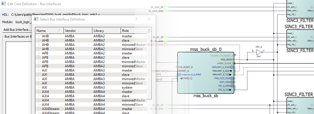
First of all, let’s take a look at the device. On one side we have the FPGA fabric, that contains all the configurable cells of the FPGA, the distributed SRAM blocks and the DSP blocks to perform operations up to 18 x 18 bits. One interesting point about this device is that the FPGA configuration is stored in the Flash configuration cells, so the FPGA does not read an external memory to be configured. This reduces the boot time, and improves the security, one of the major assets of this device. On the other side we have the Microcontroller Subsystem (MSS) that contains all the peripherals (CAN, SPI, I2C, etc.), and also the Arm Cortex-M3 processor. Similar to how the fabric stores the configuration in the Flash configuration cells, the MSS also contains an embedded Non-Volatile Memory (eNVM) to store the code to run on the Arm Cortex-M3 processor. Regarding the interface between the FPGA and the MSS, Advanced Microcontroller Bus Architecture (AMBA) interface is used with two different standards, Advanced High-Performance Bus (AHB) for high-speed interfaces (DDR, PCIe, etc.), and Advanced Peripheral Bus (APB), to connect peripherals.
As you might notice, the architecture of an SoC is very similar among all manufacturers, if they are based on Arm technologies, but in this case, you have a well-known Arm Cortex-M3 processor used for many industrial applications. In this post, I will show you how to develop a simple application using the Hello FPGA Kit a new kit from Microchip that is based on the SmartFusion2 SoC.
To begin, we need to create a new project on the Libero SoC Design Suite for the SmartFusion2 M2S010-1VFG256 device.

In the next window, we must select the default voltage of the Input/Output (I/O), the Phase Locked Loop (PLL) and the VDD supply ramp. The hardware defines these parameters which are shown in the next screen for the Hello FPGA Kit.

Next, the Libero software asks if we want to create a System builder-based design. This is a project based on microcontroller, which is our case.

When the configuration is finished, we need to select a name for the MSS, and the configuration for the MSS will open.
First, we need to define the memory where we will store the program. As I mentioned before, this device contains non-volatile memory inside, so we will use it to store the program.

When we select the data storage for the client type, a new window will open. On the M2S010 we have 256 KB of eNVM memory, and can also pre-fill the memory. For the Hello FPGA Kit, the values we select for the content section and the number of words field are not important at this moment so we can fill the fields with the values in the next figure.

Next, we select the peripherals that we want to add to our MSS. On this window, we select the MSS , which are the peripherals inside the MSS. These peripherals are essentially for communication and General-Purpose Input/Output (GPIO). On the other side we have peripherals that will be implemented on the fabric, but they will be connected to the MSS through APB interface. These peripherals will be on the MSS FIC_0 – MSS Master Subsystem. Lastly, we have peripherals from the MSS that we want to be accessed from the fabric. These peripherals will be on the MSS FIC_0 – Fabric Master Subsystem. In this example, we are going to use a Pulse-Width Modulation (PWM) peripheral from the fabric, and we want to manage it from MSS. On the configuration of the corepwm_0, we will select one channel, and we must uncheck the box Fixed Pre-Scale.

Also, to make the design easily expandable, we will enable the MM_UART_0 peripheral. It is important to change the configuration to Connect to Fabric. This configuration will allow us to connect the UART pins to any pin since the connections will be done on the Smart Design. We will also enable the MSS_GPIO peripheral, and select the connection to Fabric.
Regarding the clock, the Hello FPGA Kit has an onboard 50 MHz oscillator connected to Dedicated input path 0, so we can use it as the main oscillator. This clock will be connected to a CCC, that will generate the clock to the Arm Cortex-M3. This time we will set the M3 frequency to 100MHz. The next three tabs can be accepted by default since they are to configure the tick timer for the M3, the EDAC for RAM, and security.
On the interrupt tab, The Libero software will find and show the peripherals that have enabling interrupts, and finally, the window will show us the memory map.
Once the configuration is finished, a block that corresponds with the MSS will be instantiated onto the design. We can see the outputs and inputs corresponding with the peripherals we had selected before. To connect these I/O ’s to the FPGA pins, we can promote these connections to the top level by clicking with the right button over the pin. Pins corresponding to the clock output (CCC), must be marked as unused since there aren’t peripherals on Fabric which needs the clock signal. The same with the connections POWER_ON_RESET_N, MSS_READY and INIT_DONE. FAB_RESET_N pin will connected to VCC by Tie high option, and finally, the input TACHIN corresponding with the PWM peripheral will be configured as Tie Low. The resulting design will show as the next.

Once the Smart Design is finished, we must check the design rules, and finally, we must create the component.

Once the component is created, the next step is to clock Build Hierarchy on the Design Hierarchy tab on the left of the Libero software window, and then we will Synthesize the design on the Design Flow tab.
Once the design is synthesized, the next step is to configure the constraints to all the pins. To do so, we must click on Manage Constraints on the Design Flow tab, and open the I/O Editor on the arrow on the Edit button. A new application will open with all the inputs and outputs that we have created on the design. The pins I have selected are next. The led0 and led1 outputs are connected to the boards leds, and the PWM and UART pins are connected to the Arduino connector. The clock pin is also connected to pin N8. Once the configuration is done, we must save (commit) the changes and we can close the I/O Editor.

Now, we can continue our implementation process by double clicking on Generate Bitstream.
The next step is to develop the software on which the Arm Cortex-M3 processor will run. We will develop this with the SoftConsole Integrated Development Environment (IDE), but first we must generate the corresponding software libraries for the project. We can do this by clicking on Configure Firmware Drivers at the end of Design Flow. Then, a new window will open, with the different cores with drivers available. We must ensure that all of the cores are already downloaded. Otherwise, the cores can be downloaded on this window. We can also generate example codes for each peripheral in this step. We will generate an example for the PWM peripheral.

We must open SoftConsole, a very familiar IDE based on Eclipse IDE. We simply have to import the project generated on the Libero software , which is located in
Now, we must take into account one important thing; this project will be developed for the Hello FPGA Kit, which is a kit that does not have an integrated JTAG. Instead, it has a PIC-32 microcontroller that configures the FPGA, without debug capabilities. This means the firmware we will create has to be stored on the eNVM with the corresponding changes on the linker script. Since there is no possibility of debugging the code, we also cannot program the device. We can only configure the FPGA, writing at the same time the content of the eNVM, that involves other changes on the linker script. Luckily, Microchip includes on the example project the corresponding linker script to write the hex file on configuring time. This linker script is production_smartfusion2_execute_in_place.ld. We can modify the Build Configuration Release, to execute this script instead of debug_in_microsemi_smartfusion2_envm.ld.

Once the changes are done, we can build the project, and a .hex file will be generated. Returning to the Libero software, by clicking on Update eNVM Content on the Design Flow, we can configure the content of the eNVM. The number of words will be modified automatically.

With this change made, we can generate the bitstream again to include the content of the eNVM.
Finally, we must configure the FPGA, and as I said before, the configuration is done through a PIC-32 microcontroller, which talks to the computer though a UART port. To configure the FPGA, Microchip has developed a GUI application. To program the device, this application uses an exported version of the FPGA configuration file, so we have to export the bit file to a .DAT format. This is easy to do on the Libero software by clicking on Export Bitstream, and selecting DAT as the output format. Once generated, we can open the GUI application, and connect the board to the corresponding COM port. Now we must select the corresponding .dat file, and click on Run. The board will now be programmed with the FPGA design and also with the Arm Cortex-M3 processor program.

If all goes well, a PWM will be generated on the Arduino connector after restarting the board.
At this point, you will notice that the delay between the board at power up and the PWM signal start is very short. This is because the design is stored inside the device and the read time is lower than the read time on an external Flash through a Quad Serial Peripheral Interface (QuadSPI) port.
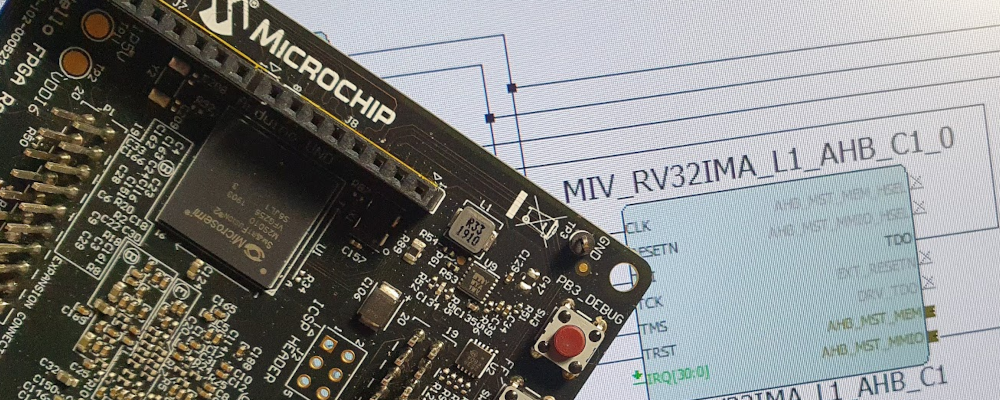
In this blog post we have used the Arm Cortex-M3 processors to develop a very simple project, but we all know that these kinds of processors, which are used in many applications from industrial to medical, are very powerful. Also, the reach that they have is enormous; We can receive support from many forums, and we can’t forget about the Cortex Microcontroller Software Interface Standard (CMSIS), which contains a very large set of libraries for many areas. On the other hand, although the SmartFusion2 SoC is a SoC based on an ARM Cortex-M3 processor, we can’t forget that it is also an FPGA, and Microchip offers its Mi-V softcore, a RISC-V processor that can be implemented on this device. It will be interesting to start developing some applications with this softcore.