Creating a RISC-V based design on SmartFusion®2 SoC.
Everybody knows that the processor of the moment is the RISC-V, even it is not a processor itself, the amount of the boards based on RISC-V is growing more and more. To understand the reason of that, we have to understand what is RISC-V, and what makes it different to Arm® or x86. First of all, we have to know that RISC-V is not a processor, like Arm or x86, they are an Instruction Set Architecture (ISA), In particular, it is an Open Instruction Set Architecture, and the open word makes the big difference between RISC-V and Arm or x86. I will explain it with an example, if I am an ASIC designer, and I want to integrate on my design a processor, I have two options, the first one and the most common until now was pay to Arm Limited, the owner of the Arm Architecture, to let me design a processor that uses their architecture, and be compliant with their instruction set. This will make my design arrive to a big number of developers that have their design compliant with the Arm architecture. The second option you have is design a RISC-V compliant processor. In this case, as the architecture is open, so you don’t have to pay to design a compliant processor. As all open-source projects, the community supporting this architecture is growing continuously, as well as the companies that are involved in the development. One of these companies is Microchip.
As we saw with the Arm Cortex®-M1 or recently with the Arm Cortex-M3, there are also available a big number of soft-cores based on RISC-V architecture to be implemented on FPGA. On this post we are going to develop a RISC-V based example design using the core available for the Microchip FPGAs, the Mi-V core.
Microchip offer several cores based on RISC-V architecture. For this project we will use the latest core developed, MiV_RV32, that is the lightest, so we will be able to make the design in Hello FPGA Kit, and has available both APB3 and AHB interfaces, that is very useful to connect the eNVM and some peripherals.

Other characteristic of RISC-V is the high configurability, we can find different RISC-V based cores according the extensions they have implemented. The extensions that are available in the core correspond to the letters that you can find following RV32, for example an RV32IMAF has the I (Base Integer Instruction Set), M (Standard Extension for Integer Multiplication and Division), A (Standard Extension for Atomic Instructions), and F (Standard Extension for Single-Precision Floating-Point). The extensions available for the MiV_RV32 core are IMC, C corresponding with (Standard Extension for Compressed Instructions).
The project we are going to develop will be based on Mi-V_RV32IMC, and since the SmartFusion2 SoC has a Microcontroller Subsystem (MSS), we will connect the Mi-V processor to the MSS in order to use the non-volatile memory (eNVM), and the SRAM available. Also, we will add a GPIO peripheral to be able to read the state of the pushbuttons, and a pulse width modulation (PWM) peripheral to manage the three LEDs of the board. In this case, the Arm Cortex-M3 processor will be disabled to save energy.
First, we have to create a new project on Libero design suite, select a name, and this time, since we won’t use the Arm Cortex-M3, we will select as part an IGLOO®2 FPGA, that is the compatible FPGA with the SmartFusion2 SoC.

Next on the voltage selector we will select 3.3 for the PLL and the I/O Settings. Now on the next window, since we will use the MSS, we will select the option Create a system builder-based design.

Once the project is created, Libero® design suite asks us a name for the system builder, in my case I select top as name. Next, the MSS configuration wizard will be opened and the memory selection window will be shown. From the MSS we will as both eNVM to store the program, and the SRAM to execute the program, so we will select the two options.

Now we have to create a memory client and for the moment we will select the option Content filled with 0s, since later we will initialize the memory with the hex file generated on SoftConsole. By clicking on Next we will select the peripherals. IN this case, the peripherals are the interface between the MSS and the fabric. We must check the box on the top of the window, click on next.

In the next window we can select the clock circuit that we want to use. The Hello FPGA Kit has an onboard 50 MHz oscillator, that we will use to feed the MSS clock circuit. The output clock of the MSS will be connected to all the fabric modules. This time is important select an appropriate clock speed because as the Mi-V core will be implemented on fabric, we can have timing issues. For now, we will select a clock for the fabric of 50 Mhz.

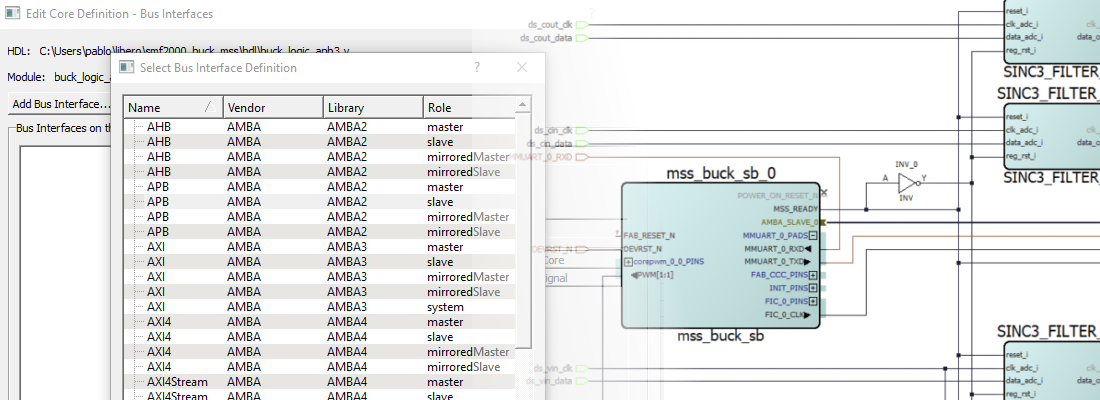
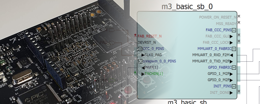
The rest of the windows will remain as default. When the wizard is finished, we will have a SmartDesign with the MSS included. Now we have to add to the design the rest of the blocks we will need. We will start with the Mi-V_RV32 core. We can find it on Catalog tab, on the folder Processors. The configurator of the core will be opened. On the first tab we have to select the extension we want to add to the core, in this case IMC, and the location of the multiplicator. Also, we can select the interface option we need, in this case APB_master for the peripherals, and AHB Master for the memory. The reset vector address will be configured to the first address on the eNVM memory on the MSS, that is 0x6000 0000.

On the Memory Map tab we have to configure the address range for the interfaces. Since the MSS has predefined addresses, we have to configure the AHB Master addresses in the range 0x2000 0000 to 0x6FFF FFFF, and the peripherals connected to the APB bus will be located on the range 0x7000 0000 to 0x7FFF FFFF.

Now the Mi-V core is configured and added to the design. Now we have to add a CoreAPB3 with two enabled APB slots to connect a corePWM with three channels, and a coreGPIO with 2 GPIO to connect the pushbuttons. The address width for the coreAPB3 is set to 16 bits.

Finally, in order to be able to debug the Mi-V core, we have to add a coreJTAG. With all the cores added to the SmartDesign, we must connect all like the next picture. To avoid warnings on the Design Rules Check, remember to mark as unused all the outputs that will remain unconnected.

With all the design complete, we must check the design rules and generate the component. Then we can synthesize the design.
Once the design is synthesized, we can set the IO constraints in order to select the input and output pins. We have to open the Constraints manager, and edit the constraints with the IO Editor, by clicking on Edit. On the IO editor window, we must select the pins according to the next image.

hen all the pins are configured, save and exit of the IO Editor, and now we can Implement the design executing Place and Route on the Design flow.
Now, since the design is implemented on fabric, we must check the timing of the design. According the handbook (pg. 7), Mi-V on SmartFusion2 SoC can achieve between 49 and 65 MHz depending the features enabled. In this case, the design runs at 50 MHz, so apparently, we won’t have any problem. To check the timing, first we must define the timing constraints for the design. To do that, we will let Libero design suite select the clock, and set the corresponding false-paths. In the Constraint Manager, we will navigate to the Timing tab and then click on Derive constraints. This will generate a file with the timing constraints for our design. We can check this file and verify that the input clock, and the output clock from the CCC are defined correctly.
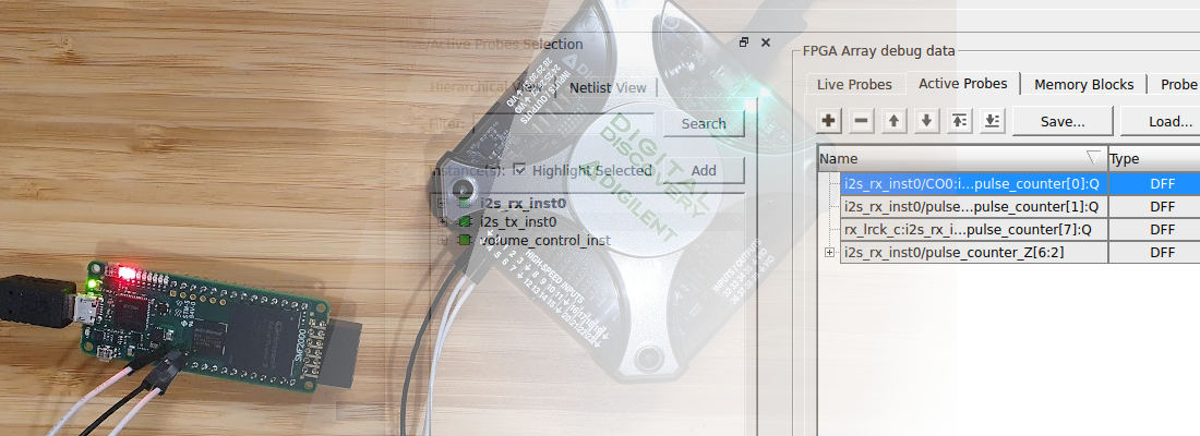
Now, on the Design Flow, we can execute the Verify Timing command and wait for the verification to finish. Then we can check a list with the signals ordered according to the worst delay.

We can see how the slowest signal has a slack of 0.608ns.
Now, we must generate all the software artifacts to use on Softconsole. To do that, we have to open the Firmware catalog that is installed by default with Libero design suite. We can see a list of all the drivers we have on our computer. In this case we need to generate the drivers for the CoreGPIO, CorePWM and MiV_RV32 Hardware Abstraction Layer (HAL).

Also, we will generate the example project PWM Slow Blink for the corePWM to use it as template.
On Softconsole, we will import the example project, and we have to make some changes. First, we have to change the addresses on the hw_platform according to the Address map.

We can see the coreGPIO in the address 0x7000 0000 and the corePWM in the address 0x7000 1000. On the hw_platform.h file we have to change the address corresponding with the corePWM and the coreGPIO, and also, we have to change the definition of SYS_CLK_FREQ to the corresponding frequency.
#ifndef HW_PLATFORM_H
#define HW_PLATFORM_H

/***************************************************************************//**
* Soft-processor clock definition
* This is the only clock brought over from the Mi-V Soft processor Libero design.
*/
#define SYS_CLK_FREQ                    25000000UL

/***************************************************************************//**
* Non-memory Peripheral base addresses
* Format of define is:
* <corename>_<instance>_BASE_ADDR
*/
#define COREGPIO_BASE_ADDR              0x70000000UL
#define COREPWM_BASE_ADDR               0x70001000UL
Now, we have to change the linker file in order to match the RAM and ROM addresses with the designed. The linker we will use is microsemi-riscv-igloo2.ld, since is the template to execute the code from eNVM. On the code we must change the envm and ram addresses.
MEMORY
{
    envm (rx) : ORIGIN = 0x60000000, LENGTH = 240k
    ram (rwx) : ORIGIN = 0x20000000, LENGTH = 64k
}

RAM_START_ADDRESS   = 0x20000000;       /* Must be the same value MEMORY region ram ORIGIN above. */
RAM_SIZE            = 64k;              /* Must be the same value MEMORY region ram LENGTH above. */
STACK_SIZE          = 2k;               /* needs to be calculated for your application */
HEAP_SIZE           = 2k;               /* needs to be calculated for your application */
Finally, on the project configuration, we have to make two more changes. First, on C/C++ Build > Settings , on the linker configuration, we have to select for the Release build configuration, the linker file microsemi-riscv-igloo2.ld.

And finally, on Flash image creation window, we have to add the flag –change-section-lma *-0x60000000

Now we can build the project to generate the hex file.
When the hex file is generated, we have to come back to Libero design suite, and initialise the eNVM memory with the hex file generated.

Finally generate the bitstream, and export it to DAT format.
Now, we have to open the Hello GUI application to send the design to the Hello FPGA Kit, and we will see how LD1 is blinking slowly.
Although RISC-V is open source and free to use, there are some companies that has cores developed and they are available to be integrated in other devices. That is the case of the PolarFire® SoC devices from Microchip, that are SOCs based on SiFive processor, a RISC-V processor from the company SiFive.
We live in changing times in silicon companies, and although Arm has a large (large, large …) number of devices in the field, RISC-V makes the development of new devices cheaper, and also the configurability that this standard offers, can help to save silicon on chips that don’t need the complete functionality. Looking forward for new SoCs with RISC-V.