EclypseZ7, Petalinux and signal processing at the edge.
 Eclypse Z7
In my last post, I said 2 things come to my mind when we talk about signal processing. One of them is FFT, and I explained you how to compute an xFFT on the Digilent’s EclypseZ7, or other Xilinx 7 series device, the other thing that I talked, was the sinc function. This function, is used, besides for book covers, to compute the coefficients of the FIR digital filters. If you need more information about sinc filters, I recommend you take a look to this book.

Unlike other kind of filters like IIR, where we have to manage Laplace transformations and differential equations, compute a FIR coefficients only depends of the sinus function. This is ideal for implement a system where FIR filter can be computed on the edge.
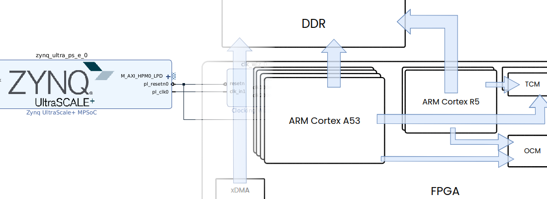
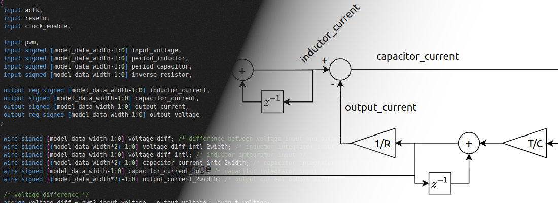
To show you what I’m talking about, I’ve design a system based in Eclypse Z7, and ZMOD DAC. Unlike the last post, where I only used the PL, in this case I will use both PL and PS. In PL will be implemented a 32 order FIR filter, ROM memory for store a signal, and the DAC driver for the AD9717. Also in PL will be a clock enable generation and clock forwarding. On the other hand, Petalinux will run in the PS, where I have develop an application to compute the coefficients of the FIR filter, according the cut frequency, gain, and window selected. This is the general diagram of the system.

First of all we have to create the input signal for FIR filter. Signal has 2 low harmonics that emulates our interest signal, 1 intermediate harmonic that emulates a low frequency perturbation, and 1 high harmonics that emulates the noise.
signal = 0.4*cos(t)+0.1*sin(5*t)+0.1*cos(10*t)+0.3*cos(30*t)

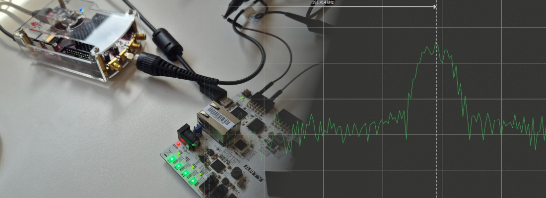
Once the signal has created, we have to set the clock period, in this case I’ve configured the clock enable for set the first harmonic in 1.95kHz, so the signals has harmonics in 1.95kHz, 9.75kHz, 19.5kHz and 58.5kHz. We have to be sure that all frequencies can be synthesized by our DAC, otherwise the signal we see in the oscilloscope may has aliasing. In case of the ZMOD DAC, the maximum sampling frequency is 125Msps, that allow us, according Nyquist – Shannon theorem, to synthesize frequencies up to 62.5MHz.
Now we have to design the FIR filter. As I said, the configuration of the FIR filter will be in the PS. For do that, we need a C application that computes the FIR coefficients and send them to the PL through AXI bus. The function for compute fir coefficients is the next:
printf("Computing fir coefficients\n");
for (i=0;i<=n;i++){
  if (i!=n/2)
    h[i] = sin(2*pi*(i-n/2)*wc)/(i-n/2);
  else
    h[i] = 2*pi*wc;
}
Notice that for use sin function, math.h library has to be added. The steps for create an application can be found on UG981, but in my case I do not follow this steps. I prefer compile application inside Petalinux, for do that you have to add the package build essentials to your root file system.
Petalinux-config -c rootfs
Filesystem packages --> misc --> packagegroup-core-buildessential
Build petalinux, and connect to the EclypseZ7 through USB or SSH.
Once do that, you can compile the application typing.
gcc -lm yourapplication.c
./a.out
The application I develop has 3 arguments, cut frecuency, filter gain and the choice of use a Hanning window or not. Cut frecuency must to be a value between 0 and 0.51000, that if for the internal conversion of the application. Gain must configured from 0 to 1100, and a value of 1 in the window argument will enable the use of window. A 0 value in window parameter disable the window.
The configuration for keep all the information of the interest signal is a cut frequency of 0.04 (argument = 40), a filter gain of 0.95 (argument = 95), and I’ve disabled the window. With this parameters, the result is as follows.
root@eclypsez7_fir:~# gcc -lm fir32driver.c
root@eclypsez7_fir:~# ./a.out 40 95 0
wc = 0.080
Computing fir coefficients
-0.013922 -0.011329 -0.007602 -0.002787 0.003020 0.009675 0.016993 0.024751 0.032698 0.040569 0.048088 0.054990 0.061024 0.065968 0.069638 0.071897 0.072659 0.071897 0.069638 0.065968 0.061024 0.054990 0.048088 0.040569 0.032698 0.024751 0.016993 0.009675 0.003020 -0.002787 -0.007602 -0.011329 -0.013922
Compute Hamming window
0.080000 0.088839 0.115015 0.157524 0.214731 0.284438 0.363966 0.450258 0.540000 0.629742 0.716034 0.795562 0.865269 0.922476 0.964985 0.991161 1.000000 0.991161 0.964985 0.922476 0.865269 0.795562 0.716034 0.629742 0.540000 0.450258 0.363966 0.284438 0.214731 0.157524 0.115015 0.088839 0.080000
Quantifying coefficients
-59795728 -48656120 -32649514 -11971062 12968666 41553940 72984184 106303528 140438336 174241072 206538480 236181760 262096496 283329728 299092224 308793504 312068480 308793504 299092224 283329728 262096496 236181760 206538480 174241072 140438336 106303528 72984184 41553940 12968666 -11971062 -32649514 -48656120 -59795728
Writting coefficients on PL


Cut frequency selected can be computed as (1e6/2)0.04 = 20e3. A cut frequency of 20e3, means at that frequency, the gain will be 0.5, that is corresponding with what we see in the spectrum.
The mix of Zynq SOCs, that allow the user combine the speed of the FPGA, and the computing power of Linux, and ZMOD DAC and ADC, allow users experiment with different signal processing techniques and apply them to circuit or simply view the results in oscilloscope.
All code can be found at Github