Mode-S decoder using USRP B210.

In engineering, specially in the FPGA field, there are several sensitive fields because of their consequences in case of failure. Those fields involve defense, space, cyber security or aviation. In in this last field where we are going to navigate deeply, more precisely in one of its communication system, the Mode Select Beacon System (MODE S). This technology allow the aircraft share its position, speed or altitude in broadcast mode, so any receiver device can receive that information and obtain the aircraft information. This technology is the reason because pages like flightradar24 exists. This pages have many MODE S receivers along the world receiving information about the different flights. In this post we are going to fly inside the MODE S frames, and I will show you how to receive and decode MODE S frames using the USRP B210 and MATLAB using the Communications Toolbox.
As a disclaimer, I have to say that I am not an expert in aviation, and the post will be focused on the reception, demodulating and decoding of this protocol.
Aircraft surveillance is very important nowadays because of the huge number of flights that are crossing out countries, and, although we can think that the size of the air space is almost infinity, the truth is that exists different highways where all the flights, according its origin and destination navigate, so know the position and the speed of all the aircraft turns very important. Throughout aviation history, there were different methods to know the aircraft’s position. Primary Surveillance Radar (PSR) was the first method, and it was based on sending of a 1 us pulse from the control tower, and measure the time that the signal spends to reach the aircraft, and be reflected and received again by the antenna. A second evolution was the Secondary Surveillance Radar (SSR). This uses the PSR and using a different frequency, the control tower was able to receive information about the aircraft. In 1990 a new evolution in aircraft surveillance was introduced, the Mode Select Beacon System (MODE S), which is used today as the main source for aircraft surveillance. In MODE S, and traffic controller sends a request (uplink) to the aircraft, and the aircraft responds (downlink) with the requested information.

The uplink frame is sent using a 1030 Mhz carrier and modulated using phase modulation (PSK), unlike the downlink format which is sent using a 1090 MHz carrier and uses amplitude modulation (ASK).
Several years later ADS-B appeared. This technology includes the word automatic, so there is no input needed from the pilot or the controller, the system sends periodically information about altitude, position of speed. Each ADS-B sending is itself contained, so we can obtain the information using only the frame received.

ADS-B, like MODE S downlink format, uses 1090 MHz as a carrier and it is modulated using ASK modulation.
In this post, we are going to focus on Mode S frames. The entire ModeS reply frame is the next. We will have a preamble of eight bits, and then a data frame that could have 56 or 112 bits. it is important to know that Mode S data is codified using Manchester encoding, so a logic one is encoded as a falling edge (1 - 0), and a logic zero is encoded as a rising edge (0 - 1).

On the data frame, we can find the next fields.

According to its DF code, we can find out the content of the message. Different DF codes are shown in the next table.
| DF | Frame content |
|---|---|
| 0 | Short ACAS |
| 4 | Surveillance altitude |
| 5 | Surveillance IDENT |
| 11 | All-call reply |
| 16 | Long ACAS |
| 17 | Extended squitter |
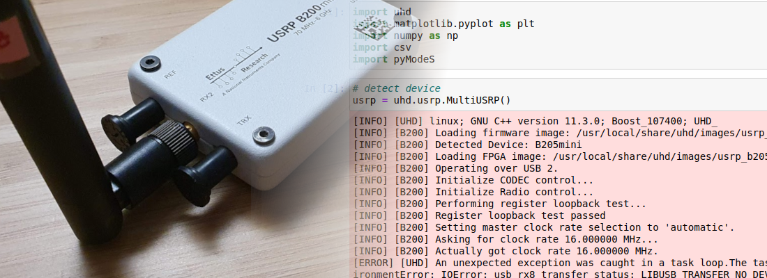
At this point, we already know the modulation method, and the carrier, so we can start to receive this signal to check how they looks. As I mentioned before, we are going to use the USRP B210, and MATLAB to first, receive the signal in Simulink, and second, decode the signal with a script.

In order to connect the USRP B210 to Simulink, we have to install the hardware support package for USRP devices. Once the USRP is HSP is installed, in Simulink we will see a new library with 2 different blocks, the first one for use by the USRP as a receiver, and the second one to use the USR as a transmitter.

For this post, we are going to use the USRP to receive a MODE S signal, so we have to add to the model the receiver block.
When the block is added, it is configured with an invalid configuration so we have to configure the SDRu receiver block. The configuration of the SDRu block configures the corresponding Radio device, in this case, the B210 board. Then since the board has more than one interface, the interface used has to be configured too. Next, we have the radio configuration. The center frequency, that is the frequency at which data is modulated, 1090 MHz for ADS-B. The sampling clock and the decimation factor will define the number of samples per bit of the frame. In this case, the MODE S frame is sent at 1 Msps, so for a clock of 10 MHz we will receive 10 samples per bit of information. The number of samples will determine the error that our receiver will allow since the data has to be read in the middle of the bit. Also, data in ModeS is sent using Manchester encoding, so the data bit has to be read in the first quarter of the byte, and then again in the third quarter, in order to determine whether the bit is one or zero. In the next figure, we can see in the left, a perfect-edged signal, and how the data is read in the first and third quarters. The right signal is a more realistic signal, where the edges are not perfect, but in this case, the sample where we will read the value of the bit is correct.

The configuration of the SDRu block is the next.

In order to be able to change the configuration of the USRP using a script, all the radio parameters are configured using variables.
% SDRu configuration

SIM_gain = 64;
SIM_clockRate = 10e6;
SIM_decimationFactor = 1;
The output format of the receiver block is configured using the parameters inside the group data. In order to configure these parameters, first we need to know the output format of the block, which is the data received from the USRP B210. The demodulation that USRP executes is complex. This means that the signal received is demodulated using 2 different signals, \(cos(fc)\), and \(sin(fc)\), the output of the cosine demodulation is the real part, and the output of the sine demodulation is the imaginary part. This kind of demodulation is very useful when we need to demodulate the signal using more complex demodulations, but in this case, in the demodulation of an ASK, we only need to know the module of the vector defined by the imaginary and the real part. In addition to the numeric format of the output, since data is acquired at a very high rate, 10 Msps in our case, the receiver block has an internal cache, to receive data at a high rate, and then, once the cache is filled with a configured number of samples, the output of the module will return a vector with all the samples, the output is deactivated until the cache is filled again.
Regarding the configuration, we can configure the Transport data type, which is the format of the data that comes from the USRP. Remember that USB is a serial protocol, so according to the width of the data, the speed will change. In this case we can select int16 or int8. Configuring int8 we can double the speed than using int16. On the other hand, the data using int8 is quantized using only 8 bits instead of 16. Besides this configuration, the block performs a transformation to a floating number again, and the parameter Output data type will configure the precision of the output data. Finally, the parameter Samples per frame will configure the size of the internal cache.
Once we have the SDRu block on the model, we can complete the model with a few more blocks. Since we need to know the value of the module of the signal, we have to add Magnitude square, thus the output of this block will be a real number. Also, since the magnitude is squared, it will help to increase the amplitude of the signal when it is greater than zero. Then, following this block, we are going to add an Unbuffer block. This block will serialize the data that the receiver block returns in blocks of 10k samples. In this way we will have a single vector with \(f_s \cdot time\) samples. Finally, since all the processing will be executed in a MATLAB script, we need to add a To workspace block to send data to the workspace. The resulting Simulink diagram is the next.

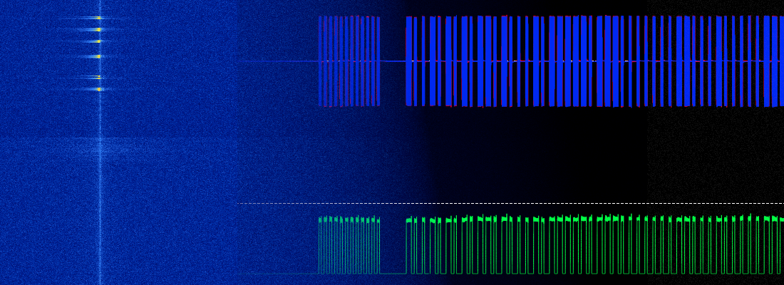
Once the Simulink diagram is complete, we can run it, and data acquired by the USRP will be sent to the workspace. In the next figure we can see how the data captured in 0.5s with the above configuration. We can see how different frames are captured, and how they can be separated from the noise level of the signal.

If we apply zoon to one of these frames, we can see the binary data modulated using ASK. The amplitude of the ones will depend of the power received. This power depends on the gain of the antenna, the power of the emitter and the distance where the aircraft is sending the signal. This amplitude can be increased by increasing the gain using the SIM_gain variable.

To extract the binary data, I have configured a threshold. Then, if the signal is greater than the threshold, it means a logic ‘1’, by contrast, if the signal is smaller than the threshold, it means a logic zero. A simple MATLAB script to extract this data is the next.
function ModeS_data = ModeS_oneFrameBinary (usrp_data, data_length, offset)

    ModeS_threshold = 0.0005;
    temp_data = [];

    ModeS_data = [zeros(1, data_length)];

    data_vector = squeeze(usrp_data);

    size(data_vector)
    for i = offset:offset+data_length
        if (data_vector(i) > ModeS_threshold)
            temp_data = [temp_data, 1];
        else
            temp_data = [temp_data, 0];
        end
    end

    ModeS_data = temp_data;

    figure
    plot(data_vector(offset:offset+data_length) * 100/1.2)
    hold on
    plot(temp_data, '-*')

end
Using this script the result is the next figure.

We can see the preamble that is a fixed binary string 10100001010000, and then the data, that is different on each frame.
Since the frame is oversampled ten times, for each bit we have 10 samples. Using the function reshape, we can split the entire data frame into groups of ten bits, and we can see the Manchester encoding.
>> ModeS_dataBits = reshape(frame,10,[]).'

ModeS_dataBits =

     1     1     1     1     1     0     0     0     0     1
     1     1     1     1     1     0     0     0     0     0
     0     0     0     0     0     0     0     0     0     0
     0     0     0     0     1     1     1     1     1     1
     0     0     0     0     1     1     1     1     1     1
     0     0     0     0     0     0     0     0     0     0
     0     0     0     0     0     0     0     0     0     0
     0     0     0     0     0     0     0     0     0     0
     0     0     0     0     1     1     1     1     1     1
     1     1     1     1     1     0     0     0     0     0
     0     0     0     0     1     1     1     1     1     1
     1     1     1     1     1     0     0     0     0     1
     1     1     1     1     1     0     0     0     0     1
     1     1     1     1     1     0     0     0     0     0
     0     0     0     0     1     1     1     1     1     1
     1     1     1     1     1     0     0     0     0     0
     0     0     0     0     1     1     1     1     1     1
     0     0     0     0     1     1     1     1     1     1
     1     1     1     1     1     0     0     0     0     1
     1     1     1     1     1     0     0     0     0     0
     0     0     0     0     1     1     1     1     1     1
     1     1     1     1     1     0     0     0     0     0
    ...
To decode the frame into hexadecimal data, we need first to decode the binary data encoded using Manchester encoding, and then convert the binary data to hexadecimal data. To decode the Manchester codification, we can read each bit in the first quarter, which for a sampling frequency of 10 Msps, will be in sample 2.5. Then we have to convert into hexadecimal each group of 4 bits. The MATLAB code that executes these actions is the next.
function hex_frame = ModeS_decodeBits (data, SIM_clockRate, SIM_decimationFactor)

% split data un groups
ModeS_dataBits = reshape(data,10,[]).';

% data decoding excluding preamble
ModeS_databin = [];

% obtain the samples where we have to read
ModeS_SamplesPerBit_Preamble= floor(SIM_clockRate / SIM_decimationFactor / 2e6);
samplesMiddleBitStart = floor((ModeS_SamplesPerBit_Preamble+0.5)/2);

% read all bits excluding preamble
for i = 9:120
    ModeS_databin = [ModeS_databin, int2str(ModeS_dataBits(i,samplesMiddleBitStart))];
end

hex_frame = dec2hex(bin2dec(reshape(ModeS_databin,4,[]).')).';

end
The result of this script, passing as an argument the variable frame which is the output of the ModeS_oneFrameBinary function is the next.
>> ModeS_dataHex = ModeS2hex(frame, SIM_clockRate, SIM_decimationFactor)

ModeS_dataHex =

    '8D34620D2358C1F3D32CA0E58B15'
Then, once the Mode S data is decoded, we can use the hexadecimal frame with the Python package pyModeS and decode the Mode S message.
import pyModeS as pms

pms.tell("8D34620D2358C1F3D32CA0E58B15")

             Message: 8D34620D2358C1F3D32CA0E58B15
        ICAO address: 34620D
     Downlink Format: 17
            Protocol: Mode-S Extended Squitter (ADS-B)
                Type: Identification and category
           Callsign:: VLG3422_

Also, using the ICAO number we can know the model of the aircraft in this page.
When I started to use SDR devices, I didn’t know that there are so many interesting signals to acquire. The fact that acquire a signal from a real aircraft and obtain information about it is very interesting, at least for me. Also, the integration with MATLAB of SDR devices like USRP makes designs with them easy, because Simulink and MATLAB are languages very common in engineering, not only USRP can be managed from MATLAB, but also the cheapest devices like RTL SDR have its hardware support package.
In short, although I have had to spend more time than usual to explore this field, it has been very interesting to learn about avionics communications and surveillance systems. For this post, I have used these two pages to obtain information and learn about Mode S, ACAS, ICAO…