Trying to hack a garage door opener with the USRP B210.
 USRP
USRP
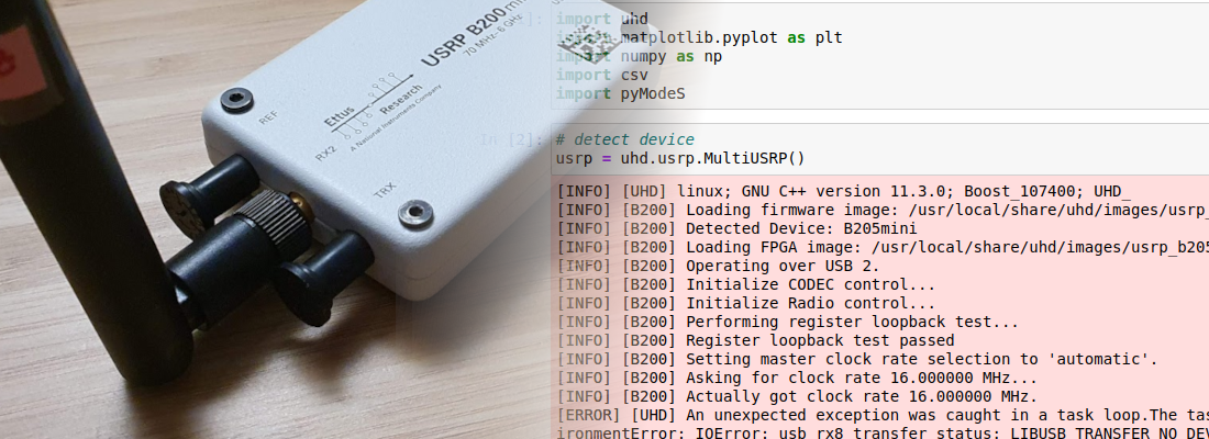
National Instruments recently released the USRP B206mini-i, a new portable SDR with a range from 70 MHz to 6 GHz with an USB-C interface compatible with most of the laptops.
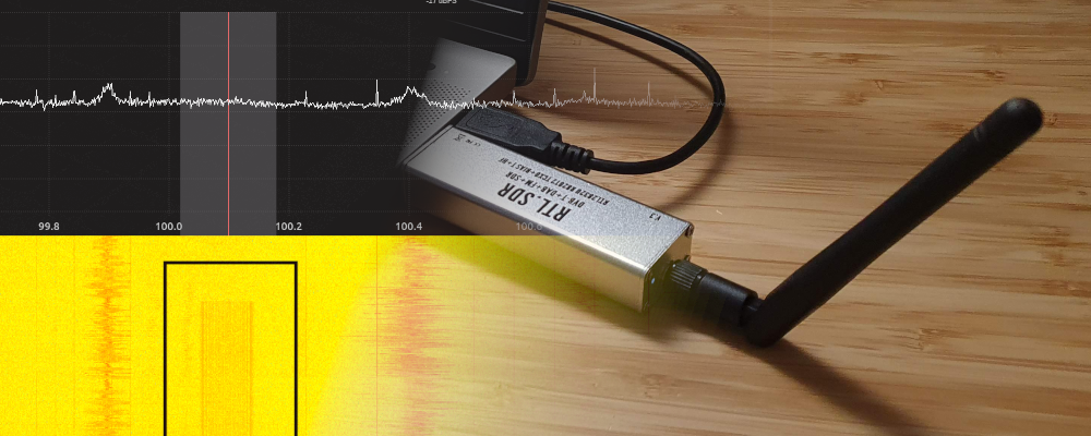
When we think about radio signals, we often think that all of them are private, impossible to decode, complicated… but nothing far than reality. It is true that acquire radio signals needs some knowledge about communications but now a days, all of the knowledge needed to acquire a radio signal is in the internet, making radio signals complex, but without complexity (this joke is a present for you :) ). In this post we will see how we can acquire a radio signal from a remote door opener, which is very easy with an SDR device like the RTL-SDR or the device I am going to use, the Ettus Research USRP B210.
The radio spectrum is infinite, we can transmit signals from a couple a Megahertz to thousands of them, but luckily for us, the spectrum is divided according its use, for example, we have a band from 30 to 300 Mhz for FM radio stations, 800 Mhz for 4G, 1500 Mhz for 5G… and, the important band for this post, 433 MHz and 869 MHz (in Europe) for the ISM band. ISM are the initials of Industrial, Scientific, Medical, that means that this band is used for this purposes. Between this purposes, the ISM band is used for weather stations, cars, wireless microphones, RFID… and remote openers for cars and garages.
Since the ISM bands are actually a group of frequencies, first of all we have to know the exact frequency where our remote opener works. To do that we can use the software Gqrx. In my case, I am using the version 2.14, since is the version that works with the USRP b210. When Gqrx is executed, the USRP b210 have to be detected, and an image will be load to the FPGA. In the configuration window we also have to configure the sample rate. For a very unknown signal, we cannot be sure which sample rate is the correct, so we can begin with a high sample rate, and then, once we know the characteristics of the signal, it can be adjusted. For this test, I have configured the sample rate to 5 Msps.

Once the device is configured we can accept the configuration and set the center frequency of the receiver. Since the ISM band in Europe, where I am, is 433 Mhz, the frequency of the remote opener will be near to that frequency, so we have to configure in the top of the window the ISm frequency. Then, press to PLAY and the receiver will start. If we push the button of the remote opener, we will see how different frames are received. The frames are “stored” in the waterfall for some seconds. Since the ISM band is widely used by weather stations, we can see periodic sequences of frames received near to 433 MHz. In my case, due to my location, only the frames from the remote opener are received.

So, now we know by where the signal of the remote is sent, then we only have to hear that band, store the samples and then replay the samples in order to hack the garage door (spoiler: No). This kind of attack is named replay, and it is very easy to execute with an SDR device like the B210. Also, in the example applications that are installed with the drivers, there are two of them that execute exactly this attack, rx_samples_to_file to read the samples and tx_samples_from_file to send the samples.
First of all, we will check that the USRP B210 is correctly detected by the PC. To verify this, we have to execute the command uhd_find_devices from any folder of our computer. This will return the name and some information of the detected device.
pablo@friday:~$ uhd_find_devices
[INFO] [UHD] linux; GNU C++ version 9.4.0; Boost_107100; UHD_4.2.0.1-0ubuntu1~focal1
--------------------------------------------------
-- UHD Device 0
--------------------------------------------------
Device Address:
    serial: 324193C
    name: MyB210
    product: B210
    type: b200
Once we have check that the device is connected, in order to store the samples of the remote control, we only have to execute the example rx_samples_to_file, with some arguments. The arguments we have to use are --freq--, in order to set the carrier frequency, --rate in order to set the sampling frequency, --gain to set the gain of the front end, and --duration to set the amount of time we want to store in the file, which is the last argument. We have to take care about the sampling frequency because, even the carrier frequency of the remote control will be close to 433MHz, configure a narrow bandwidth will increase the amount of noise. This is due to the fact that the power of the noise of a captured signal is the same regardless the sampling frequency, so if we increase the sampling frequency, the same power will be distributed over the entire bandwidth, so it will be reduced in the interesting band. For this application I have used 5 Msps of sampling frequency, but we can increase it up to 56 Msps in the USRP B210.
pablo@friday:~$ /usr/lib/uhd/examples/rx_samples_to_file --freq 434e6 --rate 5e6 --gain 40 --duration 10 remote_control_samp.dat

Creating the usrp device with: ...
[INFO] [UHD] linux; GNU C++ version 9.4.0; Boost_107100; UHD_4.2.0.1-0ubuntu1~focal1
[INFO] [B200] Detected Device: B210
[INFO] [B200] Operating over USB 3.
[INFO] [B200] Initialize CODEC control...
[INFO] [B200] Initialize Radio control...
[INFO] [B200] Performing register loopback test...
[INFO] [B200] Register loopback test passed
[INFO] [B200] Performing register loopback test...
[INFO] [B200] Register loopback test passed
[INFO] [B200] Setting master clock rate selection to 'automatic'.
[INFO] [B200] Asking for clock rate 16.000000 MHz...
[INFO] [B200] Actually got clock rate 16.000000 MHz.
Using Device: Single USRP:
  Device: B-Series Device
  Mboard 0: B210
  RX Channel: 0
    RX DSP: 0
    RX Dboard: A
    RX Subdev: FE-RX2
  RX Channel: 1
    RX DSP: 1
    RX Dboard: A
    RX Subdev: FE-RX1
  TX Channel: 0
    TX DSP: 0
    TX Dboard: A
    TX Subdev: FE-TX2
  TX Channel: 1
    TX DSP: 1
    TX Dboard: A
    TX Subdev: FE-TX1

Setting RX Rate: 5.000000 Msps...
[INFO] [B200] Asking for clock rate 40.000000 MHz...
[INFO] [B200] Actually got clock rate 40.000000 MHz.
Actual RX Rate: 5.000000 Msps...

Setting RX Freq: 434.000000 MHz...
Setting RX LO Offset: 0.000000 MHz...
Actual RX Freq: 434.000000 MHz...

Setting RX Gain: 40.000000 dB...
Actual RX Gain: 40.000000 dB...

Waiting for "lo_locked": ++++++++++ locked.

Press Ctrl + C to stop streaming...

Done!
Once we have samples acquired, we have to transmit the samples. To do that we have to use the command tx_samples_from_file, with the same arguments used in the receiver command, and also, this time, the argument --duration is not needed because the duration of the stream will be determined by the number of samples and the rate.
pablo@friday:~$ /usr/lib/uhd/examples/tx_samples_from_file --freq 434e6 --rate 5e6 --gain 60 remote_control_samp.dat

Creating the usrp device with: ...
[INFO] [UHD] linux; GNU C++ version 9.4.0; Boost_107100; UHD_4.2.0.1-0ubuntu1~focal1
[INFO] [B200] Detected Device: B210
[INFO] [B200] Operating over USB 3.
[INFO] [B200] Initialize CODEC control...
[INFO] [B200] Initialize Radio control...
[INFO] [B200] Performing register loopback test...
[INFO] [B200] Register loopback test passed
[INFO] [B200] Performing register loopback test...
[INFO] [B200] Register loopback test passed
[INFO] [B200] Setting master clock rate selection to 'automatic'.
[INFO] [B200] Asking for clock rate 16.000000 MHz...
[INFO] [B200] Actually got clock rate 16.000000 MHz.
Using Device: Single USRP:
  Device: B-Series Device
  Mboard 0: B210
  RX Channel: 0
    RX DSP: 0
    RX Dboard: A
    RX Subdev: FE-RX2
  RX Channel: 1
    RX DSP: 1
    RX Dboard: A
    RX Subdev: FE-RX1
  TX Channel: 0
    TX DSP: 0
    TX Dboard: A
    TX Subdev: FE-TX2
  TX Channel: 1
    TX DSP: 1
    TX Dboard: A
    TX Subdev: FE-TX1

Setting TX Rate: 5.000000 Msps...
[INFO] [B200] Asking for clock rate 40.000000 MHz...
[INFO] [B200] Actually got clock rate 40.000000 MHz.
Actual TX Rate: 5.000000 Msps...

Setting TX Freq: 434.000000 MHz...
Setting TX LO Offset: 0.000000 MHz...
Actual TX Freq: 434.000000 MHz...

Setting TX Gain: 60.000000 dB...
Actual TX Gain: 60.000000 dB...

Checking TX: LO: locked ...

Done!
At this point, we have stored the signal emitted by the remote opener, and then we have replayed the signal. Is it enough to hack a garage door?, well, it depends of the technology used in both the receiver and the remote control. Usually, receiver has implemented protection for replay attacks, therefore the same signal is not used twice, at least in a short period of time. So, to try to hack the remote garage door opener, we need to understand how they work. At this point we only know that the remote control works in the ISM band, but we do not have idea of how data is transmitted. In order to find out how they work, we will use GNU Radio, as we did here, and a very interesting tool named Inspectrum. Although we do not know how this remote control works, the most remote controls use the Amplitude Shift Modulation (ASK), or On-Off Keying (OOK). This modulations are very simple, and they are based on the presence or not of the carrier. When the carrier is present, is means a digital ‘1’, on the hand, when the carrier is not present means a logic ‘0’.

In order to acquire the signal transmitted by the remote control to analyze it, we will use a simple design in GNU Radio that acquires a signal, and save the samples into a file. This design stores a complex signal. If we want to acquire directly the real signal, have to add a Complex to Mag block. Acquiring the signal without this block will allow to check the sine signals before, but if we do not have interest in that signals, we can add this block to obtain directly the digital data in float format. The GNURadio design I used is the shown below. The configuration of the USRP source can be the same as used in the configuration of Gqrx, but this time the samples will be stored in a file, so the size of the file will be related with the duration, and also with the sample rate.

Now, execute the design in the USRP B210, and we have to wait executing the design until a remote control signal will be received. In the block design I have added a QT GUI Sink block in order to verify when a signal is received. When a signal is received, we can stop the design and read the content of the acquired file.
To read the file, we are going to use Inspectrum, that includes some interesting tools to decode ASK and OOK signals. Once the application is opened, we have to open the file and search the where the frame is located moving the cursor. Also we can adjust the Power max and Power min sliders in order to see the signal correctly. Once we have located the signal, we have to add two derived plot, a sample plot, where we will see the complex samples, and a amplitude plot, where we will see the real data. This last plot is what we obtain if we add in the GNU Radio design the Complex to Mag block.

At this point, we already see how a logic one is decoded when a signal is present, and a logic ‘0’ is decoded when the signal received is zero. Now in order to be able to replay the signal correctly, we have to know the bitrate, the number of bits, the duration of the frame… To find out all this parameters, we have to apply the trial and error method. In First we have to enable cursor, and then, estimate the number of bits transmitted. Now, we have to adjust the beginning and the end of the frame, and verify if all the edges match with the lines of the cursor. If there are some lines that cross the lined of the cursors, we have to change the number of bits and repeat until all the bits will match. In my case, I have used a remote controller that uses 230 bits (this is a huge frame…). This amount if bits are distributed in a preamble of 12 bits, then 10 bits of pause, and finally 197 bits of data, sent with an approx bitrate of 2.6 kbps.

In order to obtain a digital frame with Inspectrum, we can add a threshold plot in the Amplitude plot generated, and change the Power max slider to make the amplitude signal cross the threshold. Finally we can copy to the clipboard the digital data. I have follow this steps with some different frames that I have captured, and as we an expect, all of them are different. That means if we replay the same code twice, the second code will not work. This feature is used to prevent the most simple attack, the replay attack. The algorithms used to prevent this kind of attacks are different. We have some very easy hackable algorithms, where the frame sent by the remote control is shifted in each frame, therefore if the code is 01001101, next time the new code will be 10100110. But also, we have other more complex algorithms known as rolling codes. These algorithms are mostly based on random numbers generated from a seed that both emitter and receptor know, and this seed can be different for each remote opener. For example, if we live in a building with many other people that leave their cars in the same garage as ours, receptors can store different seeds for any remote opener. This is the reason because we have to activate a the remote control in the receiver.
When I started to think in this post, the title was going to be “Hacking a garage door opener with the USRP B210”, but when I learned more about the hopping code techniques, and the algorithms used to generate new codes, I was afraid to going to have to change the title, and that are good news, because our cars are safe, but how safe are? IN the case of the garage door opener I have used, 196 is a huge amount of bits, but most of them are repeated in all the different frames that I captured. data that remain stable contain information about the remote control, the state of the battery, the button pressed… and only a little amount of this bits are encrypted so, if I have interest in open the door of a garage, it is only a matter of time. I can capture the signal of many neighbors, and then extract the constant data, and the variable data, then with brute force algorithm I can obtain a valid code. In my research for this post, I have read some techniques to find out the next valid code for the receiver, for example, there is a behavior of the receivers that plays in our favor, is the fact that many receivers takes as valid the next code generated, and also a considerable amount of the next codes, in some receivers up to 250 codes (in order to still working if the user press the button and the receiver does not receive the signal), so if we find out one of these frames the code will be validated by the receiver. Also, Samy_Kamkar presented in the DEF CON conference a vulnerability of the hopping code systems. it is a kind of man in the middle. In this case, we have to jamming the signal received by the receiver and capture the signal sent by the remote control, then, when the user press the button the second time, the main in the middle sends to the receiver the first frame acquired, storing the second frame, which is valid. Then, we only have to send the second frame that will be validated by the receiver.
With this post I don’t want to try you to hack the garage of your neighbor, but if you know how they work, better, y everybody have a little idea of how they work, we can avoid mistakes that could make bad people obtain the code to hack your garage or your home. Knowledge is power!