Using an RP2040 for programming and debugging the CP SOM ONE
 CP SOM ONE
When we design a board for a programmable device, an important thing that we have to consider is how to program that board. This was the question I asked myself when I designed the CP SOM ONE. In the first version of the SOM, I added a JTAG header in the SOM to use the JTAG HS3, but this limits to that JTAG cable the ways to program the board. For the second version, I connected the JTAG pins to one of the connectors of the board, so the programming method will be defined by the carrier board. Thanks to this, I can test different ways to program the FPGA. In this post, I going to show you a very interesting method, which also is cheap and open-source, the project xvc-pico, which uses a Raspberry Pi pico as JTAG cable.
This open-source project is based on another project that uses the RP Pico as a generic JTAG, the pico-dirtyJtag.
Although the project is known bu using the Raspberry PI Pico as a JTAG, in reality, we can use just the RP2040 microcontroller with a custom board and use it as a JTAG, but remember that it is a microcontroller, so it can manage many other functions like power supply configuration, ADC references, SYZYGY DNA… in short, we can use it as a platform controller of our board.
To use the RP2040 as JTAG, first, we need to add the 99-programming-adapters.rules file, located in the project’s GitHub folder to the rules.d folder.
pablo@friday:~/git/xvc-pico$ sudo cp 99-programming-adapters.rules /etc/udev/rules.d/
pablo@friday:~/git/xvc-pico$ sudo udevadm control --reload-rules
pablo@friday:~/git/xvc-pico$ sudo udevadm trigger
Now, we can run the make the daemon, and execute it to enable the hardware server.
pablo@friday:~/git/xvc-pico/daemon$ cmake .
-- Checking for module 'libusb-1.0'
--   Found libusb-1.0, version 1.0.25
-- Configuring done
-- Generating done
-- Build files have been written to: /home/pablo/git/xvc-pico/daemon
pablo@friday:~/git/xvc-pico/daemon$ make
[ 50%] Building C object CMakeFiles/xvcd-pico.dir/xvcpico.c.o
[100%] Linking C executable xvcd-pico
[100%] Built target xvcd-pico
pablo@friday:~/git/xvc-pico/daemon$ ./xvcd-pico
write ep size = 64
XVCPI is listening now!
At this point, we can connect the FPGA to the JTAG using the following pinout.

When the FPGA board is connected and powered, we can open Vivado and click on Open target > Auto Connect. This action will create a new hardware server. Now, by doing right click on the hardware serve, we can Add Xilinx Virtual Cable (XVC). This will open a new window where we have to write the IP of the host, and set the port to 2542. If all it connected, when the configuration is done, we will be connected to the FPGA like with a regular JTAG.

Now we can program the FPGA.

In addition to Vivado, the xvc pico also can be used from Open FPGA Loader. The configuration for Open FPGA Loader is the next.
pablo@friday:~$ openFPGALoader -c xvc-client --port 2542 ./top.bit
detected xvcServer version v1.0 packet size 5120
freq 6000000 166.666667 166 0
a6 0 0 0
Open file DONE
Parse file DONE
load program
Load SRAM: [===================================================] 100.00%
Done
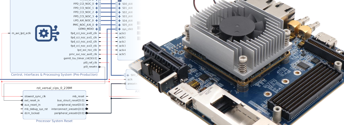
With this, we have tested the JTAG capability of the xvc_pico, but this cable also creates a serial port so we can use it to send data between the FPGA and the host computer. To test this I have created a Microblaze project for the CP SOM ONE. The configuration of the Microblaze microcontroller is quite basic.

In addition to the Microblaze, we need to add an AXI UART Lite module to add a serial port to the Microblaze microcontroller. The xvc_pico is configured by default for a baud rate of 115200 bauds, so we have to configure the IP for this baud rate.

The entire block design is the next.

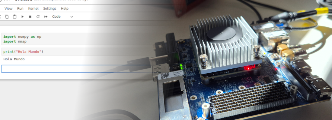
When the design is generated, we can go to Vitis to develop the software project. For this design I have used the Hello World example, making some changes in the text sent. Now, I have spent some time trying to configure the XVC on Vitis 2023.2, but that is not needed. We just have to open the JTAG on Vivado, and then we will be able to program and debug our project from Vitis. When we start the debugging session, we will see that the FPGA is programmed and the program pointer is set on the main file.

Then, to verify the behavior of the project, I have used picocom from Ubuntu, but any serial terminal can be used.
pablo@friday:~$ picocom -b 115200 /dev/ttyACM0
Finally, the output of the terminal show the configured text.

Every day more and more open-source tools are released, and day after day those tools work better. To have the chance of integrating a JTAG in all your FPGA boards just adding a chip that can be found by 1 dollar is great. Moreover, if we think that we also have a USB-UART transceiver, the cost becomes ridiculous. I am thinking now of the next FPGA board with the RP2040 as a debugger.