DMA, Petalinux and the ZUBoard-1CG
 ZUBoard
NOTE: The procedure described in this article has change with the latests Linux Kernels. I am working on a new version of this article.
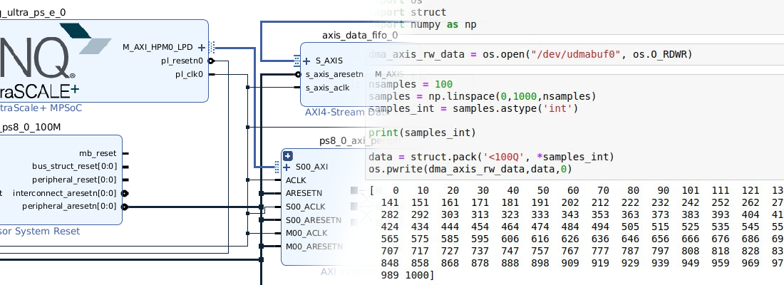
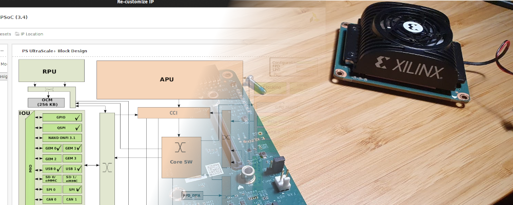
Zynq MPSOC are complex device. Complex because its Processing System (PS) is based on a heterogeneous multi-core consisting of a dual or quad ARM Cortex-A53 and a dual ARM Cortex-R5. In addition, those four or six cores are surrounded by an FPGA or Peripheral Logic (PL). But they are also complex devices, because of the way they are all connected. Every single core of the Zynq MPSOC has access to all the peripherals, and also access to the FPGA. This complete access from all to all is built using AXI (AMBA) interfaces and switches that address all the transactions. According to the route we are using, we can get a direct path for peripherals, or minimum latency in memory access. In general, transactions within the PS, are managed by itself, and we cannot select the path we want to use, but this is different when we talk about the PL. The PS has several open connections to the PL, and the designer is who will select the appropriate connection according to their needs. In the next figure, extracted from Vivado, we can see the available connections between the PL and the PS.

There are a bunch of open interfaces between PS and PL, for example, if we are designing a peripheral that for working just needs to be configured by the PS, we have to use a master AXI interface, belonging to the Low Power Domain (LPD), in particular the AXI HPM0 LPD, which connects the PL to the low power domain (LPD) switch. However, if we are designing an IP that moves a high amount of data that has to be stored in the DDR memory, we have to use an interface with direct access to the DDR memory using a DMA peripheral, we need to use a slave AXI interface that belongs to the full power domain, in particular, the AXI HP0 FPD.
The application we are going to develop in this article is closely related to AXI interfaces and DMA. In this application we are going to use the ZUBoard from AVNET, which is based on a Zynq MPSOC, and running Petalinux, we are going to configure the DMA to perform data transactions between the PL and the DDR memory. Since Vitis 2023.1 has been released a few weeks ago, we are going to develop the entire project using this version.
First, using Vivado, we have to create a new project, and then a new block design. In this block design, we need to add the Zynq MPSOC processing system, and also we are going to connect the RGB LEDS and the pushbuttons through two AXI GPIO. All of this can be connected automatically by Vivado. it is important to check the Apply Board Preset when we click over Run Block Automation.
This will be the basic block design for this board. Now, we need to enable the AXI HP0 FPD, and include in the block design the AXI DMA and also an AXI Stream Data FIFO to create a data loop. To enable the AXI HP0 FPD, we need to navigate to PL-PS interfaces of the Zynq MPSOC PS, and enable it. We are going to use a data width of 32 bits.

Regarding the DMA, we are going to create a basic module, without Scatter Gather Engine. This DMA IP will connect the PS with the peripherals that need to send data, in this case, the data FIFO, and this is needed because the interface of the PS uses an AXI Memory Mapped protocol, while the FIFO uses an AXI4 Stream protocol. The DMA IP has two AXI Memory mapped interfaces, one that takes data using AXI memory mapped and converts it to AXI4 stream (MM2S), and another one that takes data in AXI4 Stream format and converts it to AXI memory mapped (S2MM). These two interfaces are connected to the PS through an AXI interconnect. Also, the DMA has two AXI4 stream interfaces, one for each direction, that are connected to the FIFO.

Regarding the AXI Stream data FIFO, its configuration is very simple, we just need to configure the memory depth and the clock.

To use the DMA within Petalinux, we need the DMA interrupts connected to the PS, so we need to enable the interrupts input on the PS, and using a concat block, connect both interrupts of the DMA to the PS.

The complete block design of the project is the next.

Now we can generate the bitstream, and export the hardware including the bitstream. Next, we can rename the folder where the Vivado project is stored to hw, this way we have separated the hardware configuration of the project from the software configuration or the operating system.
The next step is to create the Petalinux distribution for this project.
pablo@friday:~/base_zuboard$ source /media/pablo/data_m2/xilinx/PetaLinux/2023.1/settings.sh
pablo@friday:~/base_zuboard$ petalinux-create --type project --template zynqMP --name dmazuboard
Now, following the same rule we followed with the hw folder, we can rename this folder as os.
pablo@friday:~/base_zuboard$ mv dmazuboard/ os/
pablo@friday:~/base_zuboard$ cd os/
Once the Petalinux project is created, we can set the hardware configuration.
pablo@friday:~/base_zuboard/os$ petalinux-config --get-hw-description=../hw
Within the menu that is opened, we can change the Ethernet configuration to make the board use a fixed IP, With this configuration we will be able to connect the board to our computer without using a router.
The next step is not needed, but we have to take care to ensure that all the drivers needed to use the DMA are selected in the kernel configuration. To ensure this, we can open the kernel configuration and search the configuration CONFIG_XILINX_DMA, which as I have said, has to be enabled by default.
pablo@friday:~/base_zuboard/os$ petalinux-config -c kernel

Once we have the kernel correctly configured, we need to make some steps before we can use the DMA. A difference between the DMA IP and other IP like AXI GPIO for example, is that the DMA cannot be accesed from the User Space. This means that we need a driver to use it. Fortunately, AMD has the DMA Proxy, a set of DMA driver and a DMA example application. The drivers work over the kernel drivers DMA Engine and Xilinx DMA. The code can be downloaded from Github.
To add the driver and the application to the Petalinux distribution, we need to add a module and also an application to our project. The module name will be dma-proxy, and the application will be dma-proxy-test.
pablo@friday:~/base_zuboard/os$ petalinux-create -t modules -n dma-proxy --enable
pablo@friday:~/base_zuboard/os$ petalinux-create -t apps --template c -n dma-proxy-test --enable
These commands will add two folders in our Petalinux folder tree, one of them under recipes-apps, and the other one under recipes-modules.
pablo@friday:~/base_zuboard/os/project-spec/meta-user$ tree -L 2
.
├── conf
│   ├── layer.conf
│   ├── petalinuxbsp.conf
│   └── user-rootfsconfig
├── COPYING.MIT
├── meta-xilinx-tools
│   └── recipes-bsp
├── README
├── recipes-apps
│   └── dma-proxy-test
├── recipes-bsp
│   ├── device-tree
│   └── u-boot
├── recipes-kernel
│   └── linux
└── recipes-modules
    └── dma-proxy
Now, we need to add to the folder recipes-apps/dma-proxy-test/files the source code of the application, and also the header file dma-proxy.h. Now, on recipes-apps/dma-proxy-test we need to add the makefile for this code.
APP = dma-proxy-test

# Add any other object files to this list below
APP_OBJS = dma-proxy-test.o

all: build

build: $(APP)

$(APP): $(APP_OBJS)
	$(CC) -o $@ $(APP_OBJS) $(LDFLAGS) $(LDLIBS)
clean:
	rm -f $(APP) *.o
Then, we need to add to the folder recipes-modules/dma-proxyfiles the source code of the module, and again, the header file dma-proxy.h. Now, on recipes-apps/dma-proxy we need to add the makefile for this code.
obj-m := dma-proxy.o

SRC := $(shell pwd)

all:
	$(MAKE) -C $(KERNEL_SRC) M=$(SRC)

modules_install:
	$(MAKE) -C $(KERNEL_SRC) M=$(SRC) modules_install

clean:
	rm -f *.o *~ core .depend .*.cmd *.ko *.mod.c
	rm -f Module.markers Module.symvers modules.order
	rm -rf .tmp_versions Modules.symvers
Now we need to add a node for the AXI DMA in the device tree. We can do this by adding to the system-user.dtsi the next code.
dma_proxy {
  compatible ="xlnx,dma_proxy";
  dmas = <&axi_dma_0 0  &axi_dma_0 1>;
  dma-names = "dma_proxy_tx", "dma_proxy_rx";
};
Since we enabled both the application and the module when we created them, we don’t need to do anymore. Next, build the Petalinux distribution.
pablo@friday:~/base_zuboard/os$ petalinux-build
After a few minutes, we will see how the screen turns red, which is not a good thing. Finally, the build fails. The error is related with the PMU SW.
ERROR (phandle_references): /pmu: Reference to non-existent node or label "cpu2"
ERROR (phandle_references): /pmu: Reference to non-existent node or label "cpu3"
The part which is based the ZUBoard is the variant 1CG, which only has two cores in the APU, unlike other parts from 3CG with has four cores in the APU. Seems like Petalinux does not take this into consideration when it generates the firmware for the Platform management Unit (PMU), or at least not in all the files. if we take a look to the file zynqmp.dtsi, we can see how in the configuration of the interrupts there is a reference to the non-existent cores, which causes the error in the build.
pmu {
  compatible = "arm,armv8-pmuv3";
  interrupt-parent = <&gic>;
  interrupts =  <0 143 4>,
                <0 144 4>,
                <0 145 4>,
                <0 146 4>;
  interrupt-affinity =  <&cpu0>,
                        <&cpu1>,
                        <&cpu2>,
                        <&cpu3>;
  };
In the AMD Support forum, we can find a workaround for this bug, which delete the wrong property, and redeclare it well. We can do it by editing the file system-user.dtsi.
/include/ "system-conf.dtsi"
/ {

  pmu {
      /delete-property/ interrupt-affinity;
      interrupt-affinity = <&cpu0>, <&cpu1>;
  };
};
Making this, the issue is fixed. Now we need to clean the last build and rebuild the project again.
pablo@friday:~/base_zuboard/os$ petalinux-build -x mrproper
pablo@friday:~/base_zuboard/os$ petalinux-build
Once the building is finished, we have to create the boot file.
pablo@friday:~/base_zuboard/os$ petalinux-package --boot --u-boot --fpga
[INFO] Sourcing buildtools
INFO: File in BOOT BIN: "/home/pablo/workspace_local/base_zuboard/os/images/linux/zynqmp_fsbl.elf"
INFO: File in BOOT BIN: "/home/pablo/workspace_local/base_zuboard/os/images/linux/pmufw.elf"
INFO: File in BOOT BIN: "/home/pablo/workspace_local/base_zuboard/os/project-spec/hw-description/base_zuboard_bd_wrapper.bit"
INFO: File in BOOT BIN: "/home/pablo/workspace_local/base_zuboard/os/images/linux/bl31.elf"
INFO: File in BOOT BIN: "/home/pablo/workspace_local/base_zuboard/os/images/linux/system.dtb"
INFO: File in BOOT BIN: "/home/pablo/workspace_local/base_zuboard/os/images/linux/u-boot.elf"
INFO: Generating zynqmp binary package BOOT.BIN...


****** Bootgen v2023.1
  **** Build date : Apr  7 2023-10:18:04
    ** Copyright 1986-2022 Xilinx, Inc. All Rights Reserved.
    ** Copyright 2022-2023 Advanced Micro Devices, Inc. All Rights Reserved.


[INFO]   : Bootimage generated successfully

INFO: Binary is ready.
WARNING: Unable to access the TFTPBOOT folder /tftpboot!!!
WARNING: Skip file copy to TFTPBOOT folder!!!
When the boot image is generated we can copy them with the root file system and the Linux kernel image to an SD card. The SD card has to contain two different partitions, one for the boot files, and the other one for the root file system. The partition where the boot is located has to be formatted using the FAT file system, and the partition for the root file system has to be EXT4. I have used the application disks to generate the partitions.

In the boot partition, we need to copy the boot.scr, BOOT.bin and image.ub files. On the other partition, we need to extract the content of the compressed file rootfs.tar.gz.
Finally, we need to insert the SD card on the ZUBoard, and let it boot Linux.
When Linux is running, we can check if the drivers are loaded.
dmazuboard:~$ dmesg | grep dma
[    2.727961] xilinx-vdma 80020000.dma: Xilinx AXI DMA Engine Driver Probed!!
[    3.015570] systemd[1]: Hostname set to <dmazuboard>.
[    4.217592] dma_proxy: loading out-of-tree module taints kernel.
[    4.225384] dma_proxy module initialized
[    4.239619] Creating channel dma_proxy_tx
[    4.271102] Creating channel dma_proxy_rx
Also, by executing ls /dev we will see that the peripherals dma_proxy_tx and dma_proxy_rx exist in the system. Finally, we can execute the application dma-proxy-test, and the test will be executed by sending and receiving data using the DMA.
dmazuboard:~$ dma-proxy-test 10000 128 1
DMA proxy test
Verify = 1
Normal Buffer Performance: Time: 247189 microseconds, Test size: 128000 KB, Throughput: 140 MB / sec
DMA Buffer Performance   : Time: 247364 microseconds, Test size: 128000 KB, Throughput: 139 MB / sec
Time: 21584500 microseconds
Transfer size: 1280000 KB
DMA proxy test complete
DMA peripherals have a great advantage, during a data transaction, the processor is not used, so DMA are essential in high-performance systems. In this blog we already use the DMA in several articles, for example in this article we use the DMA in a bare-metal application. Also, we have used the DMA in this project to transfer data over PCIe from a host computer to an AXI Stream IP implemented in an FPGA, and this project that we have developed today is very similar, with the great advantage that the host PC is in reality inside the same chip than the FPGA, been able to achieve high-speeds, and avoiding mechanical connections. The possibilities that SOC gives us are huge, as huge as doing things that, a few years ago, are impossible without a computer, that allows us to design low-power and small-size powerful devices.