Using the DMA and AXI4 Stream on Zynq US+.
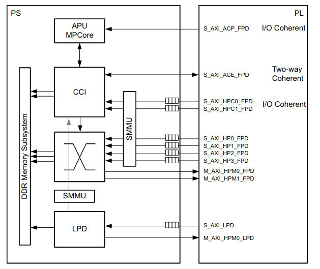
When we are working with a SOC or MPSOC, is very common the data interchange between the PL and the APU, or between the PL and the RPU. To do that, the Zynq platform gives us several interfaces between the PL and both APU and RPU aka PS. In case of Zynq MPSOC, these interfaces are described on the TRM of Zynq US+, on chapter 35. On this post, we will focus on the High Performance interfaces (S_AXI_HP0-3_FPD).
What makes interesting this interfaces is their directly connection to the DDR, without PS interaction. In other words, is a direct access to the main memory of the system, from the PL, therefore, it allows our IPs to write data on the DDR in parallel to the PS program execution. This connection is made through the System Memory Management Unit (SMMU), which basically is a unit to translate between the AXI address map, and the PS address map.
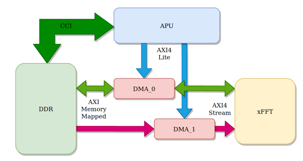
To manage that kind of transmissions, we will use the the AXI DMA IP from Xilinx. DMA stands for Direct Memory Access, and it allows data transfer between 2 memories, or one data generator, like ADC, and memory, or between memory and a data consumer like DAC. In the project that I have designed, the APU will send a signal to the xFFT IP on the PL side, and then, xFFT will send the result of the FFT again to the APU. We can catalog this example as an FFT accelerator, since the PL will compute the FFT using several multiplication threads. The data transfer diagram is shown on the next figure.
As we can see on the diagram, 2 DMA are used, DMA_0 can read and write from the xFFT to the DDR. This DMA will be used to send the signal and receive the result. The other one, the DMA_1, will be used to configure the xFFT.
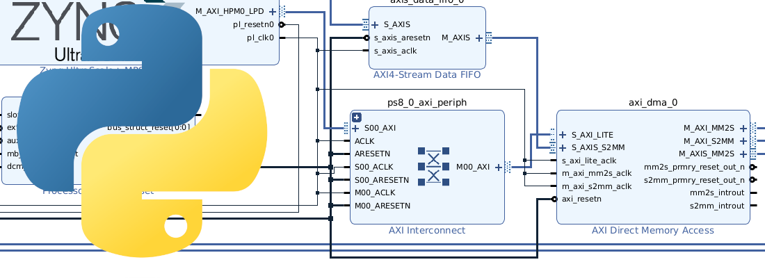
Focusing on the DMA, we can see that there are 2 AXI4 connections on each DMA. The AXI4 Lite interface will be used to configure the DMA (set source and destination addresses, start a transfer…), and the AXI4 Stream will be used to manage the data itself. Port S2MM (Stream to Memory Mapped), is used to transfer data from xFFT, to the DDR (Slave connect to xFFT, and Master to AXI interconnect), and port MM2S (Memory Mapped to Stream), will send data from DDR to the xFFT (Slave connect to AXI interconnect, and Master connect to xFFT).
Regarding the xFFT, the configuration is quite different to the one we used on this post. On that occasion, the xFFT IP was managed by a RTL code design by me, so the input/output widths could be customizable according my own IP manager. In this case, widths of input and output ports must be compliant with AXI4 widths. This affects to the FFT scaling, because regardless the length of the FFT, the output width has to be 32 or 64, but the FFT is accumulative, and the width of the final result will depends of the samples computed. To reduce the output width, xFFT allows us to apply an scaling factor to each step. This scaling factor is defined by the number of shifts applied to the result of each step, and is coded in 2 bits, that corresponds with factors of 1/1, 1/2, 1/4 and 1/8. The number of steps will depend on the algorithm used to deploy the FFT. In case of Radix-2, at each step we will obtain 2 parallel FFT, therefore, for a 64 FFT, we will have 6 steps (64/2, 32/2, 16/2, 8/2, 4/2, 2/2). In case of using Radix-4, each step will perform 4 parallel FFT, so the steps will be reduced to the half (64/4, 16/4, 4/4). In case of Radix-2, the number of DSP Slices used is lower than Radix-4, therefore, at this point, we will have to decide between save resources, using Radix-2, or improve the throughput, using Radix-4. The configuration I have selected is Radix-4, and the output scaled, so I have to configure 3 scale factors.
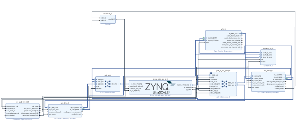
The final block design must look like the next one.
Once we have our block design complete, the bitstream generated, and the hardware exported, the next step is the design on Vitis.
To develop the C code to manage the DMAs, I’ve used the example code provided by Xilinx, xaxidma_example_simple_poll.c. This code has to be modified to add a second DMA, the signal generation, and I also have added a code for verification, that compute the 2s complement and the module of each harmonic.
/* Project FFT through DMA */

/* DMA libraries */
#include "xaxidma.h"
#include "xparameters.h"
#include "xdebug.h"

/* Math library */
#include "math.h"

/* DMA devices */
#define DMA_DEV_DATA XPAR_AXIDMA_0_DEVICE_ID
#define DMA_DEV_CONFIG XPAR_AXIDMA_1_DEVICE_ID

/* Memory data ranges */
#define DDR_BASE_ADDR XPAR_PSU_DDR_0_S_AXI_BASEADDR
#define CONFIG_PKG_LENGTH 0x4
#define DATA_PKG_LENGTH 0x100
#define N_SAMPLES 64

#define MEM_BASE_ADDR (DDR_BASE_ADDR + 0x1000000)
#define CONFIG_BUFFER_BASE (MEM_BASE_ADDR)
#define TX_BUFFER_BASE (MEM_BASE_ADDR + CONFIG_PKG_LENGTH)
#define RX_BUFFER_BASE	(TX_BUFFER_BASE + DATA_PKG_LENGTH)
#define RX_BUFFER_END	(RX_BUFFER_BASE + DATA_PKG_LENGTH)

/* xFFT configuration */
#define xFFT_FORWARD_nINVERSE 1 /* 1bit */
#define xFFT_SCALE 0x1A /*6bits */

#define xFFT_CONFIG ((xFFT_FORWARD_nINVERSE & 0x1) + ((xFFT_SCALE & 0x3f) << 1))

XAxiDma AxiDma_config; /* DMA1 instance declaration */
XAxiDma AxiDma_data; /* DMA0 instance declaration */

int main(){

	XAxiDma_Config *cfgptr_config; /*dma config configuration */
	XAxiDma_Config *cfgptr_data; /*dma data configuration*/
	int status;
	u32 *config_buffer_ptr; /* pointer to xfft configuration */
	u32 *datatx_buffer_ptr; /* pointer to tx data configuration */
	int *datarx_buffer_ptr; /* pointer to rx data configuration */
	int i;

	/* Signal variables */
	float angle = 0.0; 	/* Angle */
	float angle_inc; /* Angle increment according harmonic to synthesize */

	/* Verification */
	float abs[64];
	float re2;
	float im2;
	int re;
	int im;

	/* Pointer initialization */
	config_buffer_ptr = (u32 *)CONFIG_BUFFER_BASE;
	datatx_buffer_ptr = (u32 *)TX_BUFFER_BASE;
	datarx_buffer_ptr = (int *)RX_BUFFER_BASE;

	/* Read dma configuration */
	cfgptr_config = XAxiDma_LookupConfig(DMA_DEV_CONFIG);
	cfgptr_data = XAxiDma_LookupConfig(DMA_DEV_DATA);

	if (!cfgptr_config || !cfgptr_data) {
		xil_printf("No config found\r\n");
	}

	/* dma device initialization */
	status = XAxiDma_CfgInitialize(&AxiDma_config, cfgptr_config);
	if (status != XST_SUCCESS) {
		xil_printf("Configuration fail on DMA config\r\n");
	}

	status = XAxiDma_CfgInitialize(&AxiDma_data, cfgptr_data);
	if (status != XST_SUCCESS) {
		xil_printf("Configuration fail on DMA data\r\n");
	}

	/* Disable interrupts */
	XAxiDma_IntrDisable(&AxiDma_config, XAXIDMA_IRQ_ALL_MASK, XAXIDMA_DEVICE_TO_DMA);
	XAxiDma_IntrDisable(&AxiDma_config, XAXIDMA_IRQ_ALL_MASK, XAXIDMA_DMA_TO_DEVICE);

	XAxiDma_IntrDisable(&AxiDma_data, XAXIDMA_IRQ_ALL_MASK, XAXIDMA_DEVICE_TO_DMA);
	XAxiDma_IntrDisable(&AxiDma_data, XAXIDMA_IRQ_ALL_MASK, XAXIDMA_DMA_TO_DEVICE);

	/* Set configuration */
	config_buffer_ptr[0] = (u32)xFFT_CONFIG;

	/* Set signal vector */

	/* Sine signal */
	angle_inc = 2*3.141592/N_SAMPLES;
	for (i=0; i<DATA_PKG_LENGTH; i++){
		datatx_buffer_ptr[i] = (int)(1260*sin(3*angle)) & 0xFFFF;
		angle = angle + angle_inc;
	}

	/* Flush the buffers before the dma transfer */
	Xil_DCacheFlushRange((UINTPTR)config_buffer_ptr, CONFIG_PKG_LENGTH);
	Xil_DCacheFlushRange((UINTPTR)datatx_buffer_ptr, DATA_PKG_LENGTH);
	Xil_DCacheFlushRange((UINTPTR)datarx_buffer_ptr, DATA_PKG_LENGTH);

	/* Transfer configuration */
	status = XAxiDma_SimpleTransfer(&AxiDma_config, (UINTPTR)config_buffer_ptr, CONFIG_PKG_LENGTH, XAXIDMA_DMA_TO_DEVICE);

	if (status != XST_SUCCESS) {
		xil_printf("Configuration sending FAILED\r\n");
		while(1);
	}
	else
		xil_printf("Config data sent\r\n");

	/* Set the dma receiver */
	status = XAxiDma_SimpleTransfer(&AxiDma_data, (UINTPTR)datarx_buffer_ptr, DATA_PKG_LENGTH, XAXIDMA_DEVICE_TO_DMA);

	if (status != XST_SUCCESS) {
		xil_printf("Data receive configuration FAILED\r\n");
		while(1);
	}

	/* Perform dma transmission */
	status = XAxiDma_SimpleTransfer(&AxiDma_data, (UINTPTR)datatx_buffer_ptr, DATA_PKG_LENGTH, XAXIDMA_DMA_TO_DEVICE);

	if (status != XST_SUCCESS) {
		xil_printf("Data sending FAILED\r\n");
		while(1);
	}
	else
		xil_printf("Data sent\r\n");

	/* This code is only for verification purposes */
	for (i=0; i<N_SAMPLES; i++) {
		if ((datarx_buffer_ptr[i]>>15)&0x1)
			re = (int)((datarx_buffer_ptr[i] & 0xffff))|0xffff0000;
		else
			re = (int)((datarx_buffer_ptr[i] & 0xffff));

		if ((datarx_buffer_ptr[i]>>31)&0x1)
			im = (int)(((datarx_buffer_ptr[i] >> 16) & 0xffff))|0xffff0000;
		else
			im = (int)(((datarx_buffer_ptr[i] >> 16) & 0xffff));

		re2 = (float)(re*re);
		im2 = (float)(im*im);
		abs[i] = sqrt(re2+im2);
	}

	xil_printf("Program end\r\n");
	while(1);
}
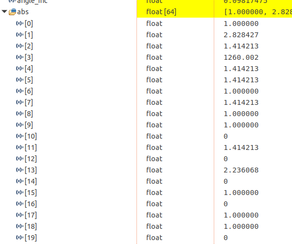
The result will appear on abs vector, and for this code, the result shows the third harmonic, and its image, with an amplitude of 1260.
On the next we will see how to change the signal generation on the C code, to an AXI4 stream IP to manage the Digilent’s ZMOD ADC.


