Adding a MicroBlaze coprocessor to an edge computer.
 Litefury
In the industry, we can find many different applications, and most of them, especially in recent years, these applications require some kind of computing. Acquiring data on where the application is, and processing the data later in any other location, maybe an office or any kind of data center is, in some cases a good option, but in many other applications, we will need to process the data and take a decision in the same place where the application is, and eventually, we will need to make this as fast as possible. This is the case, for example, of a damaged fruit detection, where the computer has to take a photo and analyze if that fruit is damaged or not, and take a decision before the fruit arrives to the box. In this application, where the processing is executed on the same application, or in other words, on the edge, we need computers with special requirements like small size, robustness and low power consumption, and these are the requirements of the edge computers.
Last Christmas I had the opportunity to use an edge computer from Advantech, in particular, I used the unit EI-52. This computer is very robust since it does not have any mechanical elements like fans or HDD. Regarding the interfaces, they are distributed between the front and the back sides, and we can find from gigabit interfaces like HDMI or Display Port, and other ports that, although they are not used in consumer electronics, but in the industry are widely used like COM ports. If we need more power, we can also run our application using units like the EPC-C Series, which are powerful and full of interfaces.

In this blog I talk about FPGA so, how can be related devices like the EI-52 or an EPC-C with the FPGA?… well, the key is the interfaces that these devices have, in particular, the PCIe interface. From my point of view, the power of this kind of computers has not to be in its processor, but in the interfaces that allow it to connect any other devices or even coprocessors, that will execute tasks while the main processor is in charge of generic tasks like communications or data storage. In this article, we are going to design a system, where we will have a host PC with a generic processor, and we are going to connect through the PCIe interface an FPGA with a soft-core implemented to use it as a coprocessor. The data shared between the host PC and the coprocessor will be stored in a DDR memory attached to the FPGA.
The board we will use is the LiteFury, a board with an M.2 format built using an Artix7 100t FPGA. Since there is no board file available for the Litefury board, we will need to define all the parameters of the board. When we are in the project creation, we have to select the part xc7a100t484tfgg-2L.

Then we will follow all the steps to create a project without selecting the source files at this moment. Once the project is created, our design will be based on a block design, thus we need to create a block design, in my case, I named this block design by adding _bd to the project name, so the block design name will be pci_mb_accel_bd.

Now we have an empty block design. The first block we are going to add is the xDMA. This module will be in charge of the PCIe interface. The Litefury board is an M.2 format board, so it has 4 PCIe lanes and the GTP transceiver included in the Artix 7 part can reach up to 6.6 Gbps, although for the PCIe interface, the maximum available speed is 5 Gbps. Regarding the DMA interface, to read and write data into memory through the DMA, we need to configure this module to use an AXI Memory Mapped interface, with 2 different channels for reading (H2C), and two for write (C2H). The xDMA module can also be configured to integrate an AXI Stream interface instead, as we used in this post.

Next, we need to connect the clock through a differential buffer. To make this connection we need to add an Utility buffer, and configure it as IBUFDS_GTE2. Finally, we need to connect a constant block configured with a value of ‘0’ to the pci_clkreq_l output.

Once the block is in the block design, we need to change the data width of the AXI interface in order to make it match the width of the memory interface.

The next module we are going to add is the Memory interface generator (MIG7) for the DDR memory. In general, this block is configured on the board file supplied by the manufacturer. In this case, RHS Research gives us a project where MIG7 block is instantiated. What I have done is create a new MIG7 block, then check the configuration in the project provided, and copy the configuration into this project, but we need to make a change. The project provided by RHS Research instantiates the xADC in order to read the temperature of the silicon. Then, this temperature is connected to the MIG7 block. This block uses the silicon temperature to make some adjustments in the delays of the DDR interface. In this project, since we do not need the xADC we will configure the MIG7 block to include the xADC instantiation within the same MIG block.

Regarding the pin out used, to avoid copy pin by pin, we can export from the original project an ucf file with the configuration of the pins. Then, in the new project we can import the pin-out configuration and verify it.

When the configuration is finished, the MIG7 block will be instantiated in the block design. Now we need to make the connections with the IOs. First, we need to connect the clock signal to an input named sys_clk. The name is important since the MIG has its own constraints file, and this pin is defined inside. Now, we need to create the interface with the DDR, it has to be named DDR. Also, I have added two of the board LEDs to verify that the MIG is well initialized.

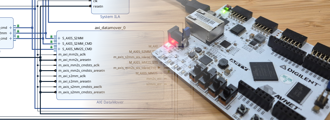
In the image below we can see the MIG7 and the xDMA block with their corresponding connections. Notice that the MIG7 block has 2 reset inputs, aresetn and `sys_rst, which are also negated, and both inputs are connected to a constant block configured with a value of ‘0’. This configuration is valid since we want that the MIG7 will be initialized at the beginning. In this case, I didn’t use a reset generator, but Vivado will add one when you click on Run block automation pop-up. You can keep the reset generator but it will only have connected one input and one output. The design has another reset generated by the XDMA block, but this will be connected to the AXI Interconnect, so it does not have to be connected directly to the MIG7.

Regarding the clock signals, MIG7 block generates a 200 MHz clock (800/4), and the xDMA runs at 100 MHz, but we do not need to manage the synchronization of these two clocks, since this will be managed by the AXI Interconnect.
Finally, we will add to the design our coprocessor, the MicroBlaze core. I have selected a Real-Time preset to include some mathematical capabilities to the core, but any of the configurations will work. The MicroBlaze will have a local memory block, and I have added ports for Data and Instructions Cache (DC and IC). These interfaces are also AXI Memory Mapped so we need to connect them to the same AXI Interconnect connected to the MIG7 block. This interface will connect the external DDR to the host PC through the PCIe interface, and also will connect the external DDR to the coprocessor, and will allow the data transfer between them. Also, I have added a BlockRAM which will act as an extension of the local memory of the Microblaze, with access also from the PCIe interface.

If we take a look at the memory map, we will note that there are some unassigned sections. This is because the default addresses will conflict. To fix that we only have to change the address range and assign them. In my case, the resulting address map is the next.

Notice that the addresses for the PCIe interface may be different from the addresses of the Microblaze. The block that will manage this will be the AXI Interconnect.
At this point we have the block design complete, so we need to Create the HDL Wrapper, and Generate the bitstream. Then once the design is implemented, we will export the hardware to create the *.xsa: file to import it on Vitis.
The next is creating the software design. Once in Vitis, we have to create the platform project which will describe the hardware where the software design will run. To create the platform we use the .xsa file created before. This platform project has to be compiled in order to generate the corresponding output files.

Now, we need to create an Application project which will run into de the platform created. The application project belongs a System which will include the application that will run on each core, in this case since we just have one core, the system will have only one project. When we create the application project, Vitis asks us if we want to use a template. In general, I use the hello world project, but this template uses an UART, and the hardware project we have created has not an AXI Uart block, so we can not use this template. In my case, I have used an empty project since we only need an application that makes the processor run. The code I used as simple as the next.
int main (void){
  int test;

  while(1){
    test = 1;
  }
}
Now we can program the board and the design is ready. Now, in the Edge computer, we need to install the xDMA drivers. Since the edge computer uses an Ubuntu server distribution, we can follow the steps described in this article to install the drivers. Once the drivers are installed, we need to reboot the edge computer.
Now, we must check if the board has been detected correctly. We can do that using the command lspci.
~$ lspci
00:00.0 Host bridge: Intel Corporation Device 9b73 (rev 03)
00:02.0 VGA compatible controller: Intel Corporation Device 9ba8 (rev 03)
00:08.0 System peripheral: Intel Corporation Xeon E3-1200 v5/v6 / E3-1500 v5 / 6th/7th/8th Gen Core Processor Gaussian Mixture Model
00:14.0 USB controller: Intel Corporation Device a3af
00:14.2 Signal processing controller: Intel Corporation Device a3b1
00:16.0 Communication controller: Intel Corporation Device a3ba
00:17.0 SATA controller: Intel Corporation Device a382
00:1c.0 PCI bridge: Intel Corporation Device a394 (rev f0)
00:1f.0 ISA bridge: Intel Corporation Device a3da
00:1f.2 Memory controller: Intel Corporation Device a3a1
00:1f.3 Audio device: Intel Corporation Device a3f0
00:1f.4 SMBus: Intel Corporation Device a3a3
00:1f.6 Ethernet controller: Intel Corporation Ethernet Connection (12) I219-V
01:00.0 Serial controller: Xilinx Corporation Device 7024
We can see that the board is detected correctly. Then, remember that we have configured the xDMA block to use two channels for write and reading. If we check the devices detected by the edge computer we can see the devices xdma0_c2h_x and xdma0_h2c_x, that are corresponding with the different xDMA channels.
~/dma_ip_drivers/XDMA/linux-kernel/tests$ ls /dev
autofs           dri          i2c-3    loop14        mem     rtc       tty0   tty20  tty32  tty44  tty56      ttyS0   ttyS20  ttyS4    vcs2   vcsu1        xdma0_control    xdma0_events_6
block            drm_dp_aux0  i2c-4    loop2         mqueue  rtc0      tty1   tty21  tty33  tty45  tty57      ttyS1   ttyS21  ttyS5    vcs3   vcsu2        xdma0_events_0   xdma0_events_7
bsg              ecryptfs     initctl  loop3         net     sda       tty10  tty22  tty34  tty46  tty58      ttyS10  ttyS22  ttyS6    vcs4   vcsu3        xdma0_events_1   xdma0_events_8
btrfs-control    fd           input    loop4         null    sda1      tty11  tty23  tty35  tty47  tty59      ttyS11  ttyS23  ttyS7    vcs5   vcsu4        xdma0_events_10  xdma0_events_9
bus              full         kmsg     loop5         nvram   sda2      tty12  tty24  tty36  tty48  tty6       ttyS12  ttyS24  ttyS8    vcs6   vcsu5        xdma0_events_11  xdma0_h2c_0
char             fuse         kvm      loop6         port    sg0       tty13  tty25  tty37  tty49  tty60      ttyS13  ttyS25  ttyS9    vcsa   vcsu6        xdma0_events_12  xdma0_h2c_1
console          gpiochip0    log      loop7         ppp     shm       tty14  tty26  tty38  tty5   tty61      ttyS14  ttyS26  udmabuf  vcsa1  vfio         xdma0_events_13  zero
core             hpet         loop0    loop8         psaux   snapshot  tty15  tty27  tty39  tty50  tty62      ttyS15  ttyS27  uhid     vcsa2  vga_arbiter  xdma0_events_14  zfs
cpu              hugepages    loop1    loop9         ptmx    snd       tty16  tty28  tty4   tty51  tty63      ttyS16  ttyS28  uinput   vcsa3  vhci         xdma0_events_15
cpu_dma_latency  hwrng        loop10   loop-control  ptp0    stderr    tty17  tty29  tty40  tty52  tty7       ttyS17  ttyS29  urandom  vcsa4  vhost-net    xdma0_events_2
cuse             i2c-0        loop11   mapper        pts     stdin     tty18  tty3   tty41  tty53  tty8       ttyS18  ttyS3   userio   vcsa5  vhost-vsock  xdma0_events_3
disk             i2c-1        loop12   mcelog        random  stdout    tty19  tty30  tty42  tty54  tty9       ttyS19  ttyS30  vcs      vcsa6  xdma0_c2h_0  xdma0_events_4
dma_heap         i2c-2        loop13   mei0          rfkill  tty       tty2   tty31  tty43  tty55  ttyprintk  ttyS2   ttyS31  vcs1     vcsu   xdma0_c2h_1  xdma0_events_5
Now, we are going to execute one of the tests included in the xDMA drivers. One of them is designed to test the xDMA using the memory-mapped interface. This test will send through the PCIe a binary file, and then it will read the data. The test checks if the data read is the same as the data written before. We need to change the test code lightly. The test will write data starting in the address 0, but in our design, the DDR memory starts in the address 0x8000 0000, so we need to increase the address offset in 2147483648, which is 0x8000 0000 in decimal. To do that we need to navigate to the tests folder.
~$ cd dma_ip_drivers/XDMA/linux-kernel/tests/
And modify the test file by adding the line addrOffset=$(($addrOffset+2147483648)) next to the addrOffset declaration.
# Write to all enabled h2cChannels in parallel
if [ $h2cChannels -gt 0 ]; then
  # Loop over four blocks of size $transferSize and write to them (in parallel where possible)
  for ((i=0; i<=3; i++))
  do
    addrOffset=$(($transferSize * $i))
    addrOffset=$(($addrOffset+2147483648))
    curChannel=$(($i % $h2cChannels))
    echo "Info: Writing to h2c channel $curChannel at address offset $addrOffset."
    $tool_path/dma_to_device -d /dev/xdma0_h2c_${curChannel} -f data/datafile${i}_4K.bin -s $transferSize -a $addrOffset -c $transferCount &
    # If all channels have active transactions we must wait for them to complete
    if [ $(($curChannel+1)) -eq $h2cChannels ]; then
      echo "Info: Wait for current transactions to complete."
      wait
    fi
  done
fi
To execute this we need to pass as an argument the amount of data we want to send, the number of transactions and the number of read and data channels. The result of the test must be the next.
~/dma_ip_drivers/XDMA/linux-kernel/tests$ sudo bash ./dma_memory_mapped_test.sh 1024 1 1 1
Info: Running PCIe DMA memory mapped write read test
      transfer size:  1024
      transfer count: 1
Info: Writing to h2c channel 0 at address offset 2147483648.
Info: Wait for current transactions to complete.
/dev/xdma0_h2c_0 ** Average BW = 1024, 12.706764
Info: Writing to h2c channel 0 at address offset 2147484672.
Info: Wait for current transactions to complete.
/dev/xdma0_h2c_0 ** Average BW = 1024, 20.844784
Info: Writing to h2c channel 0 at address offset 2147485696.
Info: Wait for current transactions to complete.
/dev/xdma0_h2c_0 ** Average BW = 1024, 56.387665
Info: Writing to h2c channel 0 at address offset 2147486720.
Info: Wait for current transactions to complete.
/dev/xdma0_h2c_0 ** Average BW = 1024, 57.424854
Info: Reading from c2h channel 0 at address offset 2147483648.
Info: Wait for the current transactions to complete.
/dev/xdma0_c2h_0 ** Average BW = 1024, 51.423695
Info: Reading from c2h channel 0 at address offset 2147484672.
Info: Wait for the current transactions to complete.
/dev/xdma0_c2h_0 ** Average BW = 1024, 52.019302
Info: Reading from c2h channel 0 at address offset 2147485696.
Info: Wait for the current transactions to complete.
/dev/xdma0_c2h_0 ** Average BW = 1024, 51.305176
Info: Reading from c2h channel 0 at address offset 2147486720.
Info: Wait for the current transactions to complete.
/dev/xdma0_c2h_0 ** Average BW = 1024, 49.214207
Info: Checking data integrity.
Info: Data check passed for address range 0 - 1024.
Info: Data check passed for address range 1024 - 2048.
Info: Data check passed for address range 2048 - 3072.
Info: Data check passed for address range 3072 - 4096.
Info: All PCIe DMA memory mapped tests passed.
If we take a look at the test code, we can see that the test uses the data stored in a file.
If all is connected properly, data will be accessible from both the edge computer and the MicroBlaze soft-core. We can check data by opening the Memory window on Vitis and selecting the address 0x8000 0000.

At this point, we have the edge computer connected through the PCIe interface to a MicroBlaze soft-core that acts as a general-purpose coprocessor where we can execute different tasks. Edge computers are very interesting devices in applications where we need a computer very close to the application, but this made that one of the requirements of these computers is the lowest consumption, making them run without fans and keeping them as simple as possible. Low power consumption also means in some cases lower performance, but by adding this kind of coprocessor we can optimize the device to execute a specific task.