Designing a FM receiver with the USRP B205mini #WorldRadioDay22.
While we are driving on the way to our jobs, we have the 99.9% of our attention on the road, but I am sure that the other 0.1% of our attention is focused on the radio. Radio has been with us for most than 100 years, and today is its day, and today is the World Radio Day. For this day I wanted to write a post dedicated to her, and also, this post will allow me to present some terms that will be used in future posts like mixers, modulation, baseband… First of all, let me explain how Radio works
Radio waves travel through the air from the radio station to the receivers. If I connect my signal generator to a wire and let the other side unconnected, the signal that I am applying is emitted through the air, but the distance and the way that this signal interacts with the obstacles will depend on the characteristics of the signal. Regardless of the way that we generate the signal we want to transmit, in every case, we will need to increase the frequency of that signal to be able to transmit the signal. That is because high-frequency signals are easy to transmit through the air. To do that we need to modulate the signal, that is exactly what I have said, elevate the frequency of the signal. To do that we use mixers, which are essentially multipliers. According to the way that we multiplicate the signals, we can find different modulation types.
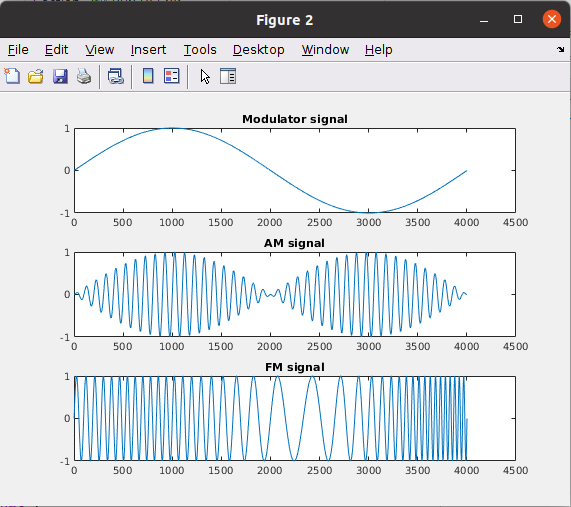
For the broadcast radio that we listen in our cars or while we are working, two methods are used, Amplitude Modulation (AM), and Frequency Modulation (FM). In the AM, the audio signal generated in the radio station, the modulator signal or the base-band signal, is multiplied by a high-frequency signal, the carrier signal, and the result is a high frequency signal which amplitude is the modulator signal. On the other hand, the FM changes the frequency of the carrier signal according to the frequency of the audio signal. In the next figure, you can see the modulator signal on the top, and the AM and FM modulation results.
The MATLAB code to obtain these plots is the next.
close all
clear all
clc

%% AM generation
fsample = 1;
nsamples = 128;

time = 0:0.00001:0.04;

carrier = sin(1e3*2*pi*time);
modulator = sin(50*pi*time);

am_signal = modulator .* carrier;

plot(am_signal)
title("AM signal")

fm_signal = sin((1e3+(modulator*200))*2*pi.*time);
figure;
plot(fm_signal)
title("FM signal")

figure;
subplot(3,1,1)
plot(modulator)
title("Modulator signal")
subplot(3,1,2)
plot(am_signal)
title("AM signal")
subplot(3,1,3)
plot(fm_signal)
title("FM signal")
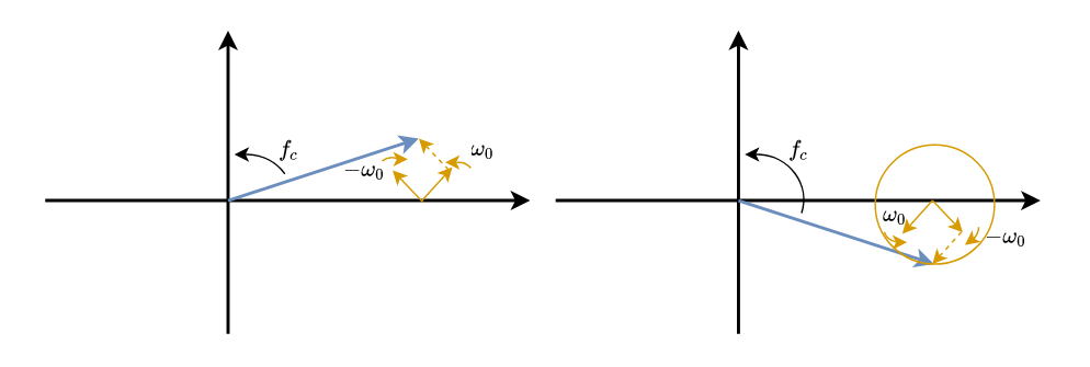
We can see this from the other point of view, from the vector’s point of view. We have a rotating vector at a speed of fc2pi, being fc the carrier frequency. Over this vector, we have the modulator signal. The modulator is represented by 2 different vectors rotating in opposite directions. For the AM modulation, the initial position of those vectors is the same, we say that those vectors are in phase. While the vectors rotate, the module of the resulting vector is kept always on the same axis, but its module is varying, its amplitude changes.
For the case of FM, the initial position of the modulator vectors are in quadrature, which is a difference of pi/2 radians between them. In this case, while the vectors are rotating, the resulting vector describes a circle. This circle is translated in changes in the speed that the resulting vector is rotating (also changes in amplitude), or what is the same, changes in the frequency that the resulting vector is rotating. In other words, the resulting vector is accelerating and decelerating according to the modulator signal.
With these very basic notions of radio signals, I will show you how you can design an FM receiver using GNURadio and USRP B205mini from Digilent. The GNURadio diagram for the FM receiver is very simple.
First of all we need to include the source of our signal. In this case, the signal is generated by the USRP so we need to include the USRP Source block. As we have said, the radio signal is modulated with a high-frequency signal, with the carrier signal, and each radio station uses a different carrier, so we need to tune the USRP in the corresponding carrier frequency. To do that we need to configure the Center Frequency, in my case I want to hear the radio station that uses the carrier 94.2 MHz. Now we have to think that we have moved the frequency spectrum 94.2 MHz to the left, so out new DC is what before was 94.2 MHz. Keep this in mind because now we have to configure the sampling frequency, and it is only 5 MHz.Then the output signal sampled at 5 MHz will be passed through a low pass filter. Audio signals have a spectrum of 20 Hz to 20 kHz, so we can attenuate all the frequencies above 20 kHz. In this case, I have configured a cut frequency of 100 kHz, with a sampling rate of 5 MHz. Also, I have used this filter to decimate the signal, that is, divide the number of samples by n. In this case, the decimation factor is 20, so the output rate will be 5 MHz divided by 20, which is 250 kHz. Next, we need to include the Wave Band FM demodulator, with a quadrature rate that is the same as the sampling frequency, 250 kHz. Finally, the sound card of most computers can manage signals with a rate of 96 kHz, so we need to resample the signal to pass from 250 kHz to 96 kHz. This block performs the operation input_samples * Interpolation / Decimation, which has as a result 96 kHz. The output of this block will be connected to the Audio sink block, and the FM receiver is complete.
In the diagram, I also have added two QT GUI Sink to check the signals in that points.
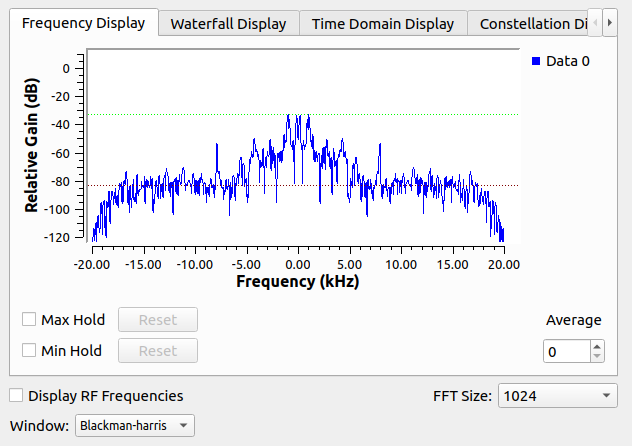
The next figure shows the frequency spectrum of the output signal. That signal contains the sound that out speakers will reproduce. We can see that the majority of the signal is contained in the first 7 kHz.
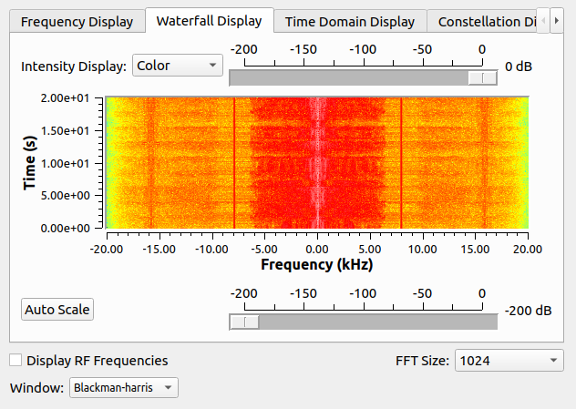
This block also allows us to see a cascade display, showing as red as more appears that frequency
Radio exists for more than 100 years, but the way that we receive and process the radio signal has changed. Inside the first receptors, we can find many inductors, capacitors, operational amplifiers, analog multipliers.. and each of those elements executes only one function. Now we only need an RF IC that is in charge of all the analog stuff for high frequency (multiplier, amplifier, filtering…), and an FPGA that is in charge of the configuration of the RF IF and all the digital processing in low frequency, that is the case of the USRP B205mini. If we want more integration in the market we can find several solutions like the Zynq US+ RFSOC that includes RF tranceivers, or the RTL2832U. Whatever, receiving and playing with radio signals is becoming easier and easier, making it more affordable for everyone. Happy World Radio Day!


