Adding the Digilent USB104 A7 board to Litex.
 USB104 A7
In this blog we already talk about Litex in this post, and also we used Litex to run Linux in a SoC in this post. If we remember the flow, the steps are very simple. We need to execute some Python scripts in order to generate the HDL code. Then, that HDL design will be implemented using Vivado, Yosys, or other of the supported tools, according the FPGA you are using. On the documentation of Litex, we can read that Litex is a framework, that provides an infrastructure. That infrastructure is based on other tools, i.e. Yosys to implement the design, or Migen, that is in charge of translate the Python code to HDL code.
In order to implement a SoC using Litex, the only we have to do is execute the Python script of the corresponding board. That script contains the definition of the board, the FPGA what is based, peripherals, connectors, IOs… so, that’s all, if we want to implement a SoC with a VexRiscv processor for the Arty board, we only need to execute the digilent_arty.py script, with the corresponding arguments and all is what we have to do to run a simple SoC. In order to implement a SoC in any other board, we only have to search in the litex-boards folder for the board, and execute it, but, what happens if the board is not in that folder? means it that the board is not supported? The answer is not. if the board is not in the litex-boards folder, only means that nobody has write the scripts to support that board. In this post we are going to create the two scripts needed to use Litex in the Digilent USB104 A7 board.
First of all we need to know that there are two different files that are needed for each board, the platform file, inside the folder platform, and the target file, that is the file we need to execute to create the system. The platform file is where all the hardware available in the board, or at least all the hardware that we want to manage from the SoC, is declared, this is the main clock port, reset port, leds and buttons… To create this file we need to know the hardware and where this IO are connected, so we will need the xdc file of the board. In the case of the USB104 board, we have this information in the Github of Digilent. Once we have this information, we need to learn ho we can declare the ports. As I mentioned before, Litex is based on Migen that the the tool in charge to convert the Python files into a FPGA files, so we need to check the Migen project manual in order learn how the ports are declared. In my case, I have check other platform scripts, and I followed this page.
In order to declare the inputs and the outputs of the board, we need to create a Python list and add to that list the IOs with the following format.
io_name, id, Pins("pin_name", "pin_name") or Subsignal(...), IOStandard("std_name"), Misc("misc"))
For example, to declare the clock and the reset ports, we can use the next code.
_io = [
    # Clk / Rst
    ("clk100",    0, Pins("E3"), IOStandard("LVCMOS33")),
    ("cpu_reset", 0, Pins("V16"), IOStandard("LVCMOS33"))
]
I have used as reset one of the buttons of the board. Then, according the xdc file, the board has also four leds, so we can add them to the script.
_io = [
    # Clk / Rst
    ("clk100",    0, Pins("E3"), IOStandard("LVCMOS33")),
    ("cpu_reset", 0, Pins("V16"), IOStandard("LVCMOS33")),

    # Leds
    ("user_led", 0, Pins("R17"),  IOStandard("LVCMOS33")),
    ("user_led", 1, Pins("P15"),  IOStandard("LVCMOS33")),
    ("user_led", 2, Pins("R15"),  IOStandard("LVCMOS33")),
    ("user_led", 3, Pins("T14"), IOStandard("LVCMOS33")),

    # Buttons
    # Button 0 used as cpu reset
    #("user_btn", 0, Pins("V16"), IOStandard("LVCMOS33")),
    ("user_btn", 1, Pins("U17"), IOStandard("LVCMOS33"))
]
Now, there are some peripherals that needs more than one pin, in Migen words, they need subsignals, for example the UART interface, the SPI FLASH and the DDR memory.
    # Serial
    ("serial", 0,
        Subsignal("tx", Pins("V12")),
        Subsignal("rx", Pins("U12")),
        IOStandard("LVCMOS33")
    ),

    # SPIFlash
    ("spiflash", 0,
        Subsignal("cs_n", Pins("L13")),
        Subsignal("clk",  Pins("L16")),
        Subsignal("mosi", Pins("K17")),
        Subsignal("miso", Pins("K18")),
        Subsignal("wp",   Pins("L14")),
        Subsignal("hold", Pins("M14")),
        IOStandard("LVCMOS33"),
    ),
    ("spiflash4x", 0,
        Subsignal("cs_n", Pins("L13")),
        Subsignal("clk",  Pins("L16")),
        Subsignal("dq",   Pins("K17 K18 L14 M14")),
        IOStandard("LVCMOS33")
    ),

    # DDR3 SDRAM
    ("ddram", 0,
        Subsignal("a", Pins(
            "R6 R7 T6 U7 T1 V7 P3 T8",
            "M6 R8 P2 P5 R1 U8 N6"),
            IOStandard("SSTL135")),
        Subsignal("ba",    Pins("V6 R2 R5"), IOStandard("SSTL135")),
        Subsignal("ras_n", Pins("M4"), IOStandard("SSTL135")),
        Subsignal("cas_n", Pins("N4"), IOStandard("SSTL135")),
        Subsignal("we_n",  Pins("U6"), IOStandard("SSTL135")),
        Subsignal("dm", Pins("U1 L1"), IOStandard("SSTL135")),
        Subsignal("dq", Pins(
            "R3 V1 T3 U4 U3 V5 T5 V4",
            "M3 L3 M2 L4 L6 K3 M1 K5"),
            IOStandard("SSTL135"),
            Misc("IN_TERM=UNTUNED_SPLIT_40")),
        Subsignal("dqs_p", Pins("U2 N2"),
            IOStandard("DIFF_SSTL135"),
            Misc("IN_TERM=UNTUNED_SPLIT_40")),
        Subsignal("dqs_n", Pins("V2 N1"),
            IOStandard("DIFF_SSTL135"),
            Misc("IN_TERM=UNTUNED_SPLIT_40")),
        Subsignal("clk_p", Pins("U9"), IOStandard("DIFF_SSTL135")),
        Subsignal("clk_n", Pins("V9"), IOStandard("DIFF_SSTL135")),
        Subsignal("cke",   Pins("N5"), IOStandard("SSTL135")),
        Subsignal("odt",   Pins("P4"), IOStandard("SSTL135")),
        Subsignal("reset_n", Pins("K6"), IOStandard("SSTL135")),
        Misc("SLEW=FAST"),
    ),
Migen also allow to declare complex connectors, that is, a group of pins that can be used for different purposes. This elements are declared in the scrips as connector. In this case I have declares the three PMOD ports. The board also have a SYZYGY port, but this is a high speed connector that is not useful manage from a CPU.
_connectors = [
    ("pmoda", "F4 F3 E2 D2 H2 G2 C2 C1"),
    ("pmodb", "C4 B2 B3 B4 B1 A1 A3 A4"),
    ("pmodc", "C5 C6 B6 C7 A5 A6 B7 D8"),

]
Finally, we can import some python functions in order to add support for some PMOD boards, for example the USB PMOD IO, I2S2 PMOD, or SD CARD PMOD.
Finally, we needs to create the platform itself, adding all the elements we have declared before. We have to create a class where we need to pack the definitions to configure the platform. In this function we have to add also the configuration that we would add to the xdc file, for example, the confgiuration of the width of the bus for reead the FLSH memory, or the command to create de mcs file. Also we have to configure the programmer with the function create_programmer. The software used to program the FPGA is OpenOCD, so we need to have it installed. Finally we need to create a third function name do_finalize. The code for the USB104 A7 board is the next.
# Platform -----------------------------------------------------------------------------------------

class Platform(XilinxPlatform):
    default_clk_name   = "clk100"
    default_clk_period = 1e9/100e6

    def __init__(self, toolchain="vivado"):
        XilinxPlatform.__init__(self, "xc7a100tcsg324-1", _io, _connectors, toolchain=toolchain)
        self.toolchain.bitstream_commands = \
            ["set_property BITSTREAM.CONFIG.SPI_BUSWIDTH 4 [current_design]"]
        self.toolchain.additional_commands = \
            ["write_cfgmem -force -format bin -interface spix4 -size 16 "
             "-loadbit \"up 0x0 {build_name}.bit\" -file {build_name}.bin"]
        self.add_platform_command("set_property INTERNAL_VREF 0.75 [get_iobanks 34]")

    def create_programmer(self):
        return OpenOCD("openocd_xc7_ft2232.cfg", "bscan_spi_xc7a100t.bit")

    def do_finalize(self, fragment):
        XilinxPlatform.do_finalize(self, fragment)
        self.add_period_constraint(self.lookup_request("clk100", loose=True), 1e9/100e6)
Now we have configured the platform file, that is the file closest to the board. The other file, although it also depends of the board and the hardware attached, I recommend to start with the target file of other similar board, and then make some modifications. In any case, I will explain what we can find on this file, and the configurations we need to change. In my case, I have used the target file of the Arty board. This board uses the same part (in the 100t variant of the Arty), they are similar in terms of the hardware they have, both have a DDR memory but different size, PMODS, same FLASH memory. The main difference id that the Arty board have an ethernet connections while the USB104 don’t. So, lets go.
With the digilent_arty.py file opened, and changed the name by digilent_usb104a7.py, first we need to change the platform that is imported, since we need to import the usb104 platform.
from litex_boards.platforms import digilent_usb104a7
Then, the DDR memory is different. We have a 256 MB RAM for the Arty board, and a 512 MB for the USB104 board, so need to update the import from litedram.modules. Fortunately, the DDR memory that have the USB104 is also available in LiteDram so we only have to change it.
from litedram.modules import MT41K256M16
Regarding the reset button in the _CRG class, Arty board has a dedicated reset button that is negated, since the USB104 have no dedicated reset button, and we have used as reset one of the user buttons. We also leave the design without reset, but I think that a reset is important. The problem of using a user button as reset, is its polarity, since the user button on the USB104 is not negated, so we need to change it. In addition, I have eliminated the choice of connect or not connect the reset in the arguments of the __init__ function.
# Clk/Rst.
clk100 = platform.request("clk100")
rst    = platform.request("cpu_reset")
Notice that the target file request to the platform the configuration of some ports, and this request is made by name, so we have to keep the same port names in the platform and the target file.
The next class is the BaseSoC, that defines the features of the softcore. In this class are declared all the peripherals that we can connect to the softcore. In the Arty file there are some arguments in the init function about the ethernet connections that we have to delete in the USB104 file.
with_ethernet=False, with_etherbone=False, eth_ip="192.168.1.50", eth_dynamic_ip=False,
Then we have to delete the configuration of the ethernet.
# Ethernet / Etherbone ---------------------------------------------------------------------
if with_ethernet or with_etherbone:
  self.submodules.ethphy = LiteEthPHYMII(
  clock_pads = self.platform.request("eth_clocks"),
  pads       = self.platform.request("eth"))
  if with_ethernet:
    self.add_ethernet(phy=self.ethphy, dynamic_ip=eth_dynamic_ip)
  if with_etherbone:
    self.add_etherbone(phy=self.ethphy, ip_address=eth_ip)
Also, in the configuration of the DRAM in the same function, we have to change the RAM module to the USB104 module.
# DDR3 SDRAM -------------------------------------------------------------------------------
if not self.integrated_main_ram_size:
  self.submodules.ddrphy = s7ddrphy.A7DDRPHY(platform.request("ddram"),
    memtype        = "DDR3",
    nphases        = 4,
    sys_clk_freq   = sys_clk_freq)
  self.add_sdram("sdram",
    phy           = self.ddrphy,
    module        = MT41K256M16(sys_clk_freq, "1:4"),
    l2_cache_size = kwargs.get("l2_size", 8192)
  )
Next we have the main function, with all the arguments that we can pass when we create the Litex SoC. In the Arty board, there are some arguments relative to the ethernet connection that we have to delete.
ethopts.add_argument("--with-ethernet", action="store_true", help="Enable Ethernet support")
ethopts.add_argument("--with-etherbone", action="store_true", help="Enable Etherbone support.")

target_group.add_argument("--eth-ip", default="192.168.1.50", type=str, help="Ethernet/Etherbone IP address.")
target_group.add_argument("--eth-dynamic-ip", action="store_true", help="Enable dynamic Ethernet IP addresses setting.")
Then in the soc variable declaration, we need to delete the arguments of the BaseSoC we have deleted before. The final soc declaration is the next.
soc = BaseSoC(
  toolchain      = args.toolchain,
  sys_clk_freq   = int(float(args.sys_clk_freq)),
  with_jtagbone  = args.with_jtagbone,
  with_spi_flash = args.with_spi_flash,
  with_pmod_gpio = args.with_pmod_gpio,
  **soc_core_argdict(args)
)
Then if the SoC is configured to have SD card support, the script needs to add one of the two functions that are declared in the platform. To access to those functions needs to know the name of the file, and since the name of the platform file has changed, we need to update it.
if args.sdcard_adapter == "numato":
  soc.platform.add_extension(digilent_usb104a7._numato_sdcard_pmod_io)
else:
  soc.platform.add_extension(digilent_usb104a7._sdcard_pmod_io)
This is the last modification that we have to make in the file. At this points we have all ready to create a SoC and verify that we have not break the files… We have to execute the new script and wait some minute.

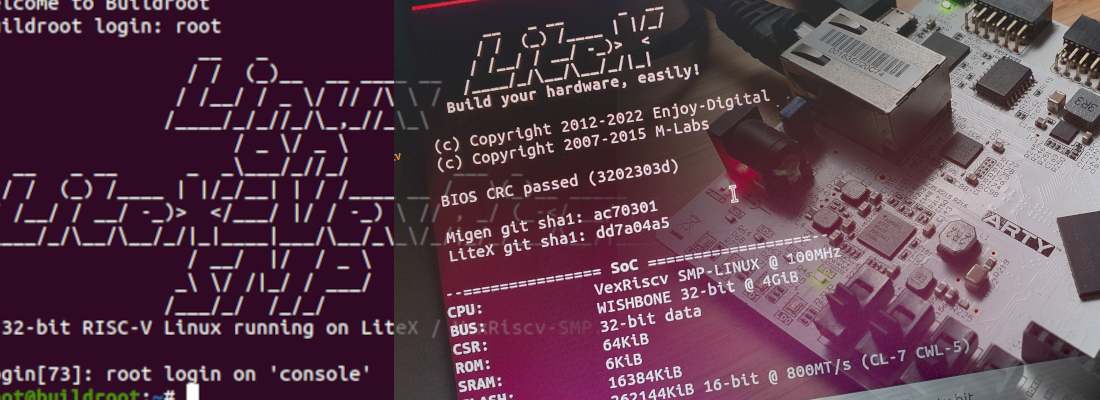
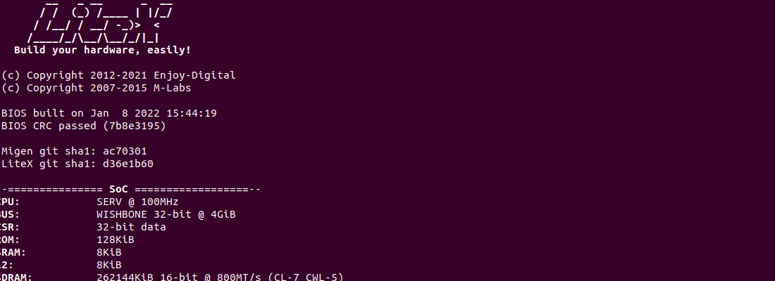
When the implementation is finished, we can connect to the board using the litex_term application, and… drumroll…

The SoC is running! Also we see the leds blinking and we can manage the leds.
There are many (many, many…) projects in the internet, supported sometimes by companies, and sometimes by the users. These last ones, are very interesting if you want to learn something because in general, all is open and accessible, and even your case was not supported at the beginning, you can use what the rest of users did to create, improve and add support for your case in the project. In this case I wanted to use the USB104 A7 board to develop some projects, and Litex is needed for one, so the only chance I had was add the USB104 to the Litex supported boards, and it was easiest than I expected, even with my poor knowledge of Migen! Now, we can use the USB104 board to make some experiments using Litex! Stay connected!