Building a SoC with Litex.
 Arty A7
There are many cases where we will need a processor inside our FPGA. In my case, soft cores are very useful when I have to implement in the FPGA a manager for an external device using high level interfaces like ethernet or modbus. For this interfaces we can find in the internet examples written in c very easily. Also, the amount of logic that we will need if we use RTL to implement this interface in some cases is larger than the logic used by a little processor and their memory. For Xilinx devices, we can use a Microblaze core that in many cases will be an goop option. In case that we are using a Microchip FPGA, Mi-V processors based on RISC-V is an excellent option. Both processors are highly configurable, allowing us to disable or enable different modules in the case of Microblaze, or by selecting the extensions for the Mi-V processor we can optimize the amount of logic used. Also, although these soft-cores are no open-source, we can use them in our design without pay a fee, but many times, these soft-core provided by the vendors do not met our requirements, or maybe we need more customization, so we will need other options.
In GitHub you can find an uncountable number of soft-cores developed by developers or companies that can be exactly what we need in terms of capabilities, resources used, configuration, or perhaps we only want to develop the entire project with open source tools. Also, if we decouple our soft-core of the device vendor, we can move our design between devices of different vendors without many issues.
At this point, we know that we have many options of soft-core that we can use, so we need to download the corresponding repository, create a project with the corresponding tool and then implement and test the core. If we are in the prototyping step of the project, we will need to make many test in order to select the most adequate soft-core to our design. For a hardware developer like me, is not a big deal to instantiate different soft cores on the design, write the constraints file and create and connect the corresponding peripherals, but it requires time. Also, could be possible that the project will be mostly a software project, so the test be done by a software developer with a minimum experience in hardware development. In this cases we need a tool that allows a software developer implement a soft core in an FPGA, and also that the time required for the implementation of the FPGA design will be the minimum as possible. Both things are offered by Litex, a tool from Enjoy Digital.
According its documentation,
The LiteX framework provides a convenient and efficient infrastructure to create FPGA Cores/SoCs, to explore various digital design architectures and create full FPGA based systems.
In other words, it is a framework to create SoCs based in different soft cores easily and very fast. The tool is based on Migen, that is a python-based tool to create RTL modules from Python code. In addition to the soft-cores, Litex integrates some peripherals written in Migen that can be connected to the soft-core using Python. Let’s see it with an example. First of all we need to download and install the Litex tool. This can be done following the steps of the Quick start guide. Once we have followed the guide, we will have the following directory tree.
pablo@friday:~/litex$ tree -d -L 1
.
├── amaranth
├── build
├── fpga_101
├── litedram
├── liteeth
├── litehyperbus
├── liteiclink
├── litejesd204b
├── litepcie
├── litesata
├── litescope
├── litesdcard
├── litespi
├── litex
├── litex-boards
├── migen
├── pythondata-cpu-blackparrot
├── pythondata-cpu-cv32e40p
├── pythondata-cpu-ibex
├── pythondata-cpu-lm32
├── pythondata-cpu-microwatt
├── pythondata-cpu-minerva
├── pythondata-cpu-mor1kx
├── pythondata-cpu-picorv32
├── pythondata-cpu-rocket
├── pythondata-cpu-serv
├── pythondata-cpu-vexriscv
├── pythondata-cpu-vexriscv-smp
├── pythondata-misc-tapcfg
├── pythondata-misc-usb_ohci
├── pythondata-software-compiler_rt
├── pythondata-software-picolibc
└── riscv64-unknown-elf-gcc-8.3.0-2019.08.0-x86_64-linux-ubuntu14
We can see the folders for the different peripherals like litespi, litepcie or even litejesd204b. Other cores code are available in /litex/litex/soc/cores. On the bottom we can see folders for the different soft-cores (cpu) that are available by default in Litex like Minerva, PicoRV32, Serv, VexRiscv, or others with 64bit architecture like Rocket. Notice that if we navigate inside one of these folders, we can see that the processor is defined in Python using Migen. Finally, if we navigate into litex-boards/litex_boards/platforms we can see a list of python files for the definition of many boards based on Gowin, Xilinx, Intel and Freescale. These files are the definition of the all the peripherals that we can find in the board, with the name, and the pins used. For this post I will use the Arty a35t board from Digilent, that is supported natively by Litex. If we navigate to litex-boards/litex_boards/targets, we can see also python files for different boards. These files will use the file in the platform folder in order to allocate the different cores and connect them to the corresponding pins. Nothing better to see this compiling an example.
We are going to navigate to the targets folder, and execute the python file corresponding to the digilent arty board with the argument –help.
pablo@friday:~/litex/litex-boards/litex_boards/targets$ ./digilent_arty.py --help
usage: digilent_arty.py [-h] [--toolchain TOOLCHAIN] [--build] [--load] [--variant VARIANT]
                        [--sys-clk-freq SYS_CLK_FREQ] [--with-ethernet | --with-etherbone]
                        [--eth-ip ETH_IP] [--eth-dynamic-ip] [--with-spi-sdcard | --with-sdcard]
                        [--sdcard-adapter SDCARD_ADAPTER] [--no-ident-version] [--with-jtagbone]
                        [--with-spi-flash] [--with-pmod-gpio] [--output-dir OUTPUT_DIR]
                        [--gateware-dir GATEWARE_DIR] [--software-dir SOFTWARE_DIR]
                        [--include-dir INCLUDE_DIR] [--generated-dir GENERATED_DIR]
                        [--no-compile-software] [--no-compile-gateware] [--csr-csv CSR_CSV]
                        [--csr-json CSR_JSON] [--csr-svd CSR_SVD] [--memory-x MEMORY_X] [--doc]
                        [--bus-standard BUS_STANDARD] [--bus-data-width BUS_DATA_WIDTH]
                        [--bus-address-width BUS_ADDRESS_WIDTH] [--bus-timeout BUS_TIMEOUT]
                        [--cpu-type CPU_TYPE] [--cpu-variant CPU_VARIANT]
                        [--cpu-reset-address CPU_RESET_ADDRESS] [--cpu-cfu CPU_CFU] [--no-ctrl]
                        [--integrated-rom-size INTEGRATED_ROM_SIZE]
                        [--integrated-rom-init INTEGRATED_ROM_INIT]
                        [--integrated-sram-size INTEGRATED_SRAM_SIZE]
                        [--integrated-main-ram-size INTEGRATED_MAIN_RAM_SIZE]
                        [--csr-data-width CSR_DATA_WIDTH] [--csr-address-width CSR_ADDRESS_WIDTH]
                        [--csr-paging CSR_PAGING] [--csr-ordering CSR_ORDERING] [--ident IDENT]
                        [--ident-version IDENT_VERSION] [--no-uart] [--uart-name UART_NAME]
                        [--uart-baudrate UART_BAUDRATE] [--uart-fifo-depth UART_FIFO_DEPTH]
                        [--no-timer] [--timer-uptime] [--l2-size L2_SIZE]
                        [--synth-mode SYNTH_MODE]
This command will show us all the customization arguments that we can pass in order to implement the SoC in the Arty board. Next to the output that I have shown you, you will find an explanation of each argument. We will check the argument –cpu-type, that is used to select the soft-core that we want to implement in out SoC.
 --cpu-type CPU_TYPE   Select CPU: None, external, lm32, mor1kx, microwatt, serv, femtorv,
                        picorv32, minerva, vexriscv, vexriscv_smp, ibex, cv32e40p, rocket,
                        blackparrot, zynq7000, eos-s3, gowin_emcu, (default=vexriscv).
Change the soft-core implemented is as easy as change the value of this argument. In addition to the soft cores, there are also two hard cores that we can use with Litex, the Zynq7000 core, and the Gowin EMCU core. For the moment we will use the default core, the VexRiscv.
Now we have to execute some steps separately, or together. First we need to create all the Verilog files that implements the soft core and the peripherals. We can do that simply executing the python file with the corresponding arguments. This step will generate all the Verilog files, and also a tcl script to implement the design in Vivado. Once the Verilog files are generated, we have to synthesize and implement this Verilog files in order to obtain a bit file. Finally, we have to write this design in the FPGA. The first step is made by Migen. This tool will read the python files and will translate them into a Verilog files. The second step, in case of a Xilinx part, can be made by Vivado or Yosys. The final step is the configuration of the FPGA, that can be made from Vivado and its Hardware manager, or using Open OCD. For the example I will use Vivado as a implementation tool, and Open OCD as configuration tool. This configuration allow me to automatize all the process, since we only need to execute the next command.
pablo@friday:~/litex/litex-boards/litex_boards/targets$ ./digilent_arty.py --build --load
NOTE: At this point you will need the RiscV GCC added to your path. With Litex, a RiscV toolchain is download under the directory riscv64-unknown-elf-gcc-8.3.0-2019.08.0-x86_64-linux-ubuntu14
You will need to add the bin folder of this directory to your path, in order to be able to compile the BIOS application.
We will see how, after the migen has finished, Vivado is executed to generate all the output files. With the default configuration, using a VexRiscv processor you will notice that the design is implemented in a couple of minutes, which is faster than a design using Microblaze. if we open the Vivado project created, and generate a post implementation utilization report, we can see that the VexRiscv processor uses 1993 LUTs. The default configuration of this soft core has a WishBone interface, an open source hardware computer bus that we can use to communicate different peripherals with the core. This interface will be equivalent to an AXI interface.

If we compare this VexRiscv processor, in terms of utilization, with a Microblaze, according the Quick start guide from Xilinx, we can see that the minimum number of logic cells used is 1900 (1% of XC7A200T).

The difference is that Microblaze is a closed processor, and VexRiscv is a RiscV processor which we can program using several open source tools.
If your soft-core requirements are very low, I mean, you need the core to execute some simple code, you can use other soft core like the developed by Olof Kindren, which is the smallest RiscV processor, and its utilization is only 562 LUTs.

Notice that to use the SerV core instead of the VexRiscv core, the only that I had to do is change the argument –cpu-type, isn’t that amazing?
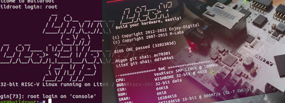
Once the design is implemented and load into the FPGA, we can use any terminal application to connect the board with the PC, and we will see a simple BIOS application that is load by default.
pablo@friday:~/litex/litex-boards/litex_boards/targets/build/digilent_arty$ lxterm /dev/ttyUSB1
__ _ __ _ __
/ / (_) /____ | |/_/
/ /__/ / __/ -_)> <
/____/_/\__/\__/_/|_|
Build your hardware, easily!
(c) Copyright 2012-2021 Enjoy-Digital
(c) Copyright 2007-2015 M-Labs
BIOS built on Jan 8 2022 15:44:19
BIOS CRC passed (7b8e3195)
Migen git sha1: ac70301
LiteX git sha1: d36e1b60
--=============== SoC ==================--
CPU: SERV @ 100MHz
BUS: WISHBONE 32-bit @ 4GiB
CSR: 32-bit data
ROM: 128KiB
SRAM: 8KiB
L2: 8KiB
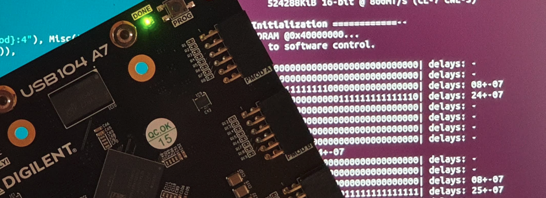
SDRAM: 262144KiB 16-bit @ 800MT/s (CL-7 CWL-5)
Typing help we can see the available commands.
--============= Console ================--

litex> help

LiteX BIOS, available commands:

help                     - Print this help
ident                    - Identifier of the system
crc                      - Compute CRC32 of a part of the address space
flush_cpu_dcache         - Flush CPU data cache
flush_l2_cache           - Flush L2 cache
leds                     - Set Leds value

boot                     - Boot from Memory
reboot                   - Reboot
serialboot               - Boot from Serial (SFL)

mem_list                 - List available memory regions
mem_read                 - Read address space
mem_write                - Write address space
mem_copy                 - Copy address space
mem_test                 - Test memory access
mem_speed                - Test memory speed

sdram_init               - Initialize SDRAM (Init + Calibration)
sdram_cal                - Calibrate SDRAM
sdram_test               - Test SDRAM
sdram_force_rdphase      - Force read phase
sdram_force_wrphase      - Force write phase
sdram_mr_write           - Write SDRAM Mode Register
This BIOS can be updated with our own application compiled with the RiscV Toolchain. For the Arty board there is an example application in the folder /litex/litex/litex/soc/software/demo. This application can be built using the next command bu using the build path of the corresponding design in the targets folder.
pablo@friday:~/litex/litex/litex/soc/software/demo$ litex_bare_metal_demo --build-path=/home/pablo/litex/litex-boards/litex_boards/targets/build/digilent_arty/
But this command for me does not work returning me the next error.
ablo@friday:~/litex/litex/litex/soc/software/demo$ litex_bare_metal_demo --build-path=/home/pablo/litex/litex-boards/litex_boards/targets/build/digilent_arty/
Traceback (most recent call last):
  File "/usr/lib/python3/dist-packages/pkg_resources/__init__.py", line 2453, in resolve
    return functools.reduce(getattr, self.attrs, module)
AttributeError: module 'litex.soc.software.demo.demo' has no attribute 'main'

During handling of the above exception, another exception occurred:

Traceback (most recent call last):
  File "/usr/local/bin/litex_bare_metal_demo", line 11, in <module>
    load_entry_point('litex', 'console_scripts', 'litex_bare_metal_demo')()
  File "/usr/lib/python3/dist-packages/pkg_resources/__init__.py", line 490, in load_entry_point
    return get_distribution(dist).load_entry_point(group, name)
  File "/usr/lib/python3/dist-packages/pkg_resources/__init__.py", line 2854, in load_entry_point
    return ep.load()
  File "/usr/lib/python3/dist-packages/pkg_resources/__init__.py", line 2445, in load
    return self.resolve()
  File "/usr/lib/python3/dist-packages/pkg_resources/__init__.py", line 2455, in resolve
    raise ImportError(str(exc))
ImportError: module 'litex.soc.software.demo.demo' has no attribute 'main'
I can workaround this error by executing directly the python script.
pablo@friday:~/litex/litex/litex/soc/software/demo$ python demo.py --build-path=/home/pablo/litex/litex-boards/litex_boards/targets/build/digilent_arty/
cp: -r not specified; omitting directory '/home/pablo/litex/litex/litex/soc/software/demo/__pycache__'
cp: -r not specified; omitting directory '/home/pablo/litex/litex/litex/soc/software/demo/demo'
 CC       isr.o
 CC       donut.o
 CC       helloc.o
 CC       main.o
 CC       demo.elf
 chmod -x demo.elf
 OBJCOPY  demo.bin
 chmod -x demo.bin
At the end, a bin file has to be generated. To charge the application in the board, we can use the next command.
pablo@friday:~/litex/litex/litex/soc/software/demo$ lxterm /dev/ttyUSB1 --kernel=demo.bin

        __   _ __      _  __
       / /  (_) /____ | |/_/
      / /__/ / __/ -_)>  <
     /____/_/\__/\__/_/|_|
   Build your hardware, easily!

 (c) Copyright 2012-2021 Enjoy-Digital
 (c) Copyright 2007-2015 M-Labs

 BIOS built on Jan  8 2022 19:07:07
 BIOS CRC passed (eb15b36e)

 Migen git sha1: ac70301
 LiteX git sha1: d36e1b60

--=============== SoC ==================--
CPU:		VexRiscv @ 100MHz
BUS:		WISHBONE 32-bit @ 4GiB
CSR:		32-bit data
ROM:		128KiB
SRAM:		8KiB
L2:		8KiB
SDRAM:		262144KiB 16-bit @ 800MT/s (CL-7 CWL-5)
When the demo application is loaded, we can see different commands
--============= Liftoff! ===============--

LiteX minimal demo app built Jan  8 2022 19:01:37

Available commands:
help               - Show this command
reboot             - Reboot CPU
led                - Led demo
donut              - Spinning Donut demo
helloc             - Hello C
Both the demo application and the BIOS application use only the 4 leds as outputs. If we want to add the RGB leds, we have to add a kind of handler for those outputs. First, in the platform folder, we need to open the corresponding file with the digilent arty board, and check if the RGB leds are declared. We can see under the _io, that the 4 RGB leds are declared, so we only need to add them into the target folder file.
_io = [
    # Clk / Rst
    ("clk100",    0, Pins("E3"), IOStandard("LVCMOS33")),
    ("cpu_reset", 0, Pins("C2"), IOStandard("LVCMOS33")),


    # Leds
    ("user_led", 0, Pins("H5"),  IOStandard("LVCMOS33")),
    ("user_led", 1, Pins("J5"),  IOStandard("LVCMOS33")),
    ("user_led", 2, Pins("T9"),  IOStandard("LVCMOS33")),
    ("user_led", 3, Pins("T10"), IOStandard("LVCMOS33")),

    ("rgb_led", 0,
        Subsignal("r", Pins("G6")),
        Subsignal("g", Pins("F6")),
        Subsignal("b", Pins("E1")),
        IOStandard("LVCMOS33"),
    ),
    ("rgb_led", 1,
        Subsignal("r", Pins("G3")),
        Subsignal("g", Pins("J4")),
        Subsignal("b", Pins("G4")),
        IOStandard("LVCMOS33"),
    ),
    ("rgb_led", 2,
        Subsignal("r", Pins("J3")),
        Subsignal("g", Pins("J2")),
        Subsignal("b", Pins("H4")),
        IOStandard("LVCMOS33"),
    ),
    ("rgb_led", 3,
        Subsignal("r", Pins("K1")),
        Subsignal("g", Pins("H6")),
        Subsignal("b", Pins("K2")),
        IOStandard("LVCMOS33"),
    ),
In the target folder file, we need to add this peripheral and add a handler of type GPIOOut. In the digilent_arty.py file we can see how the rest of the leds and the peripherals are defined. At the end of them we need to add the new handler of GPIOOut type.
led_rgb_0 = platform.request("rgb_led", 0)
self.submodules.led_rgb_0 = GPIOOut(led_rgb_0)

led_rgb_1 = platform.request("rgb_led", 1)
self.submodules.led_rgb_1 = GPIOOut(led_rgb_1)
Now we can re-build the design. This time, since we have added a new peripheral, we will need to know the address that the framework has assigned to the new peripheral. To know the address we will ask to Litex that generates the documentation. Litex uses Sphinx to auto generate the documentation, so we will need to install the dependencies, among other python packages that will be required. We can execute the command and wait to see the different errors. To add the documentation generation, we need to add the argument –doc.
pablo@friday:~/litex/litex-boards/litex_boards/targets$ ./digilent_arty_35t.py --build --load --doc
Now when it finish, in the folfer /targets/build/digilent_arty/doc/_build/html, we can open the index.html file and we will se a webpage with all the peripherals.

If we click over the LED_RGB_0 we can see the address assigned, and the bits used of the register, that are 3, one for each color. The same for the LED_RGB_1.
Now from the BIOS, we can use the command mem_write to manage the RGB leds.
litex> mem_write 0xf0001800 2
Finally, if we want to add the management of the RGB leds, we have to modify the demo application. In the demo application folder, we can see several files.
pablo@friday:~/litex/litex/litex/soc/software/demo$ tree -L 1
.
├── demo
├── demo.bin
├── demo.py
├── donut.c
├── helloc.c
├── hellocpp.cpp
├── __init__.py
├── isr.c
├── linker.ld
├── main.c
├── Makefile
├── __pycache__
└── README.md
We will modify the helloc.c to change the color of the led when this file will be executed. To do that, the helloc.c file will look like this.
#include <stdio.h>
#include <generated/csr.h>

/* leds */
#define CSR_RGB_BASE (CSR_BASE + 0x1800L)

void helloc(void) {

  static int i = 0;

  i++;

  printf("C: Hello, world!\n");
  csr_write_simple(i&0x7, CSR_RGB_BASE);

}
We have added the library csr.h, that contains the base address of the peripherals. Then, we have defined the address of the RGB leds as CSR_RGB_BASE. Finally, after the prinft we have added a memory write instructions, csr_simple_write, that writes in the RGB leds address the upper count stored in i.
If we load this application we can see that the code runs without issues.
Time ago I wanted to write about using different soft-cores, but the time that I have for the blog is not all that I want, and to make a soft-core work in an FPGA seemed a long time task. Few weeks ago I knew Litex, and after an hour of fixing dependencies, adding the Riscv toolchain to the path, and some minor issues easy to fix, I had tested 2 different soft cores. Litex is an excellent choice to investigate with different soft-cores, and don’t think that easy to works means simple, since with Litex you can develop projects using fast and complex interfaces like PCIe (a project with the LiteFury?) . Now I am already thinking in many posts using Migen itself and Yosys, and continue discovering open source tools for FPGA, that are every day more and more, and it is an excellent news because if we make that work with FPGAs more affordable, the developments with them will be more easy to front, and the community will grow.