Running Petalinux on a Microblaze soft core.
 USB104 A7
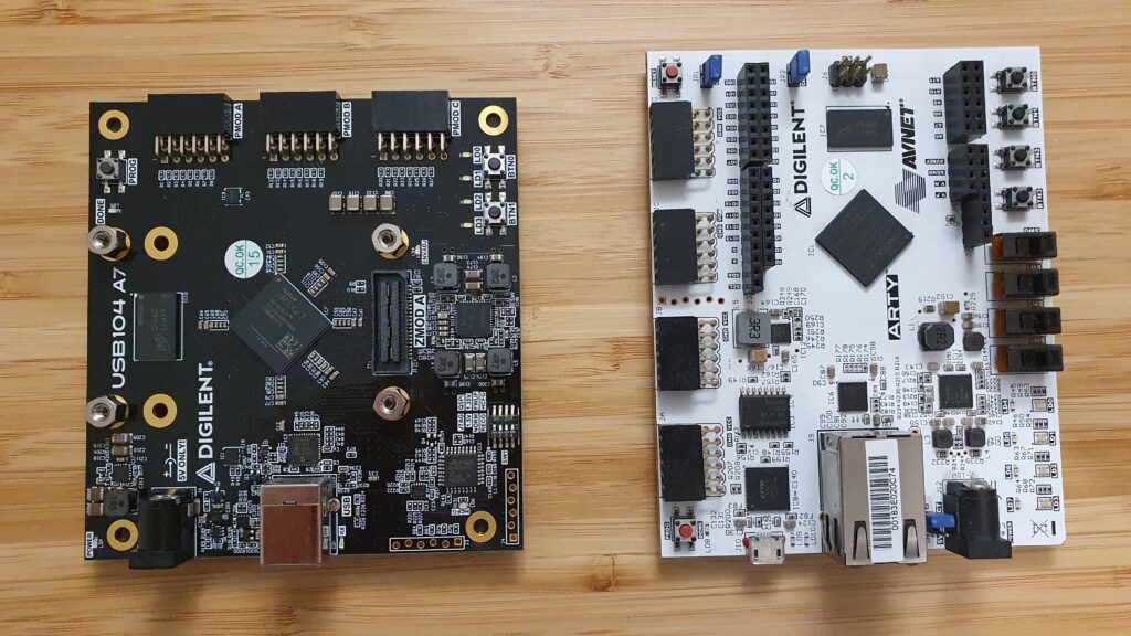
You can do everything with an FPGA. I have used this sentence many times in my job, and most of them followed by, its all a time matter. Also, in this blog I have said many times that FPGA are very adaptable devices, and they fit in many projects. In addition, in the projects where microprocessors are used, SOC have found a niche and are being used more and more. But not only a SOC fits in a project where microprocessors are used, FPGA with to a soft-core, is also a very good choice if you need some specific features. In this post I will show you how we can run Petalinux in a Microblaze soft-core. The board I will use is the Digilent’s USB104 A7. This board is based on Artix 7 100T, like the Arty 100T board, but includes twice of RAM memory and a SYZYGY port. On the other side, the Ethernet port has been removed.
[
As usual, we must create a new project, and select the USB104 A7 as the board to use. Then we have to create a block design. In the block design created, first of all we are going to add the DDR3 block from the Board tab (on the left of the block design). This, will add a MIG block with 2 clock inputs and a DDR3 interface. Although this board has many shared things with the Arty A7 100T, in this board the DDR is different. First of all, in the Arty we have 256 MB, unlike the USB104 A7 that has 512 MB. Also, the power supply of the DDR chip in the Arty board is 1.35 V, that limit the speed of the DDR up to 666 Mhz, on the other hand, in the USB104 A7, the voltage of the DDR is configurable through a switch, and can be 1.35 V, with the same maximum speed that the Arty board, or can be 1.5 V, which allows the DDR runs up to 800 MHz. The default configuration of the MIG block is for 1.5 V, so if you want to reduce the power consumption of the board, you have to make some modifications in the MIG configuration.
Coming back to the block design, we have to delete the clock inputs added automatically, and create a different clock schema. We have to connect the input clock (100 MHz), directly to the sys_clk_i input. Then, the additional clock generated by the MIG ui_addn_clk_0, which is configured to 200MHz, has to be connected to the clk_ref_i input. This schema will make that out design logic run at 100MHz, while the DDR will run at an effective frequency of 400 MHz. The ui_clk, in this case will have a frequency of 100 MHz. (This rare configuration, without MMCM to generate the clock for the MIG block, is a workaround for an issue. (More info here.) The reset input has to be connected to the reset button of the board, that is the BTN0. The Reset can also be dragged from the Board tab. Notice the the reset input is active low, and the BTN0 has direct logic, so the reset port will be connected through a inverter.

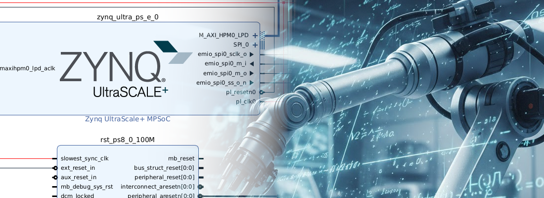
Then, we have to add the Microblaze itself. In the Run Block Automation window we will make a very basic configuration of the processor.

Then, once the Microblaze is added to the block design, we have to reconfigure it. First, in the first window, we will select the configuration as Linux with MMU.

Then in the seventh page, we have the configuration of the data and instructions cache. We will increase both to the maximum, that is 64 kB.

Finally, in the last window, we will enable all the AXI interfaces. Then, back into the block design, we will clock on Run Connection Automation.
Once the design is connected, to run the OS, we need to add some additional IP.
- AXI Timer, with both timers enabled, and the interrupt connected.
- AXI Uartlite, with the interrupt connected.
In the design, I have also added an axi_gpio, to manage the LEDs of the board and the push-button, and an axi_quad_spi to allow the communication with the FLASH memory.
The complete block design is shown in the next figure.

Once the block design is complete, we have to create the wrapper, generate the bitstream and export the hardware.
Now, we are going to start the Petalinux build. First, we need to add the Petalinux environment variables to the path.
pablo@friday:~/petalinux/2021.2$ source settings.sh
PetaLinux environment set to '/home/pablo/petalinux/2021.2'
WARNING: /bin/sh is not bash!
bash is PetaLinux recommended shell. Please set your default shell to bash.
WARNING: This is not a supported OS
INFO: Checking free disk space
INFO: Checking installed tools
INFO: Checking installed development libraries
INFO: Checking network and other services
WARNING: No tftp server found - please refer to "UG1144 2021.2 PetaLinux Tools Documentation Reference Guide" for its impact and solution
Next, we have to create a new project using the Microblaze template.
pablo@friday:~/petalinux/2021.2/projects_2021.2$ petalinux-create --type project --template microblaze --name linux_mb
INFO: Create project: linux_mb
INFO: New project successfully created in /home/pablo/petalinux/2021.2/linux_mb
Now, we will add the hardware description to the Petalinux project.
pablo@friday:~/petalinux/projects_2021.2/linux_mb$ petalinux-config --get-hw-description ../../../xilinx/petalinux_mb_usb104/
[INFO] Sourcing buildtools
INFO: Getting hardware description...
INFO: Renaming ptlnx_mb_bd_wrapper.xsa to system.xsa
[INFO] Generating Kconfig for project
In this configuration, we will exit without apply changes. Finally, we will build the Petalinux distribution for the USB104 A7.
pablo@friday:~/petalinux/projects_2021.2/linux_mb$ petalinux-build
[INFO] Sourcing buildtools
[INFO] Building project
[INFO] Sourcing build environment
[INFO] Generating workspace directory
INFO: bitbake petalinux-image-minimal
NOTE: Started PRServer with DBfile: /home/pablo/petalinux/projects_2021.2/linux_mb/build/cache/prserv.sqlite3, IP: 127.0.0.1, PORT: 43105, PID: 237643
Loading cache: 100% |############################################| Time: 0:00:01
Loaded 5131 entries from dependency cache.
Parsing recipes: 100% |##########################################| Time: 0:00:01
Parsing of 3476 .bb files complete (3474 cached, 2 parsed). 5133 targets, 693 skipped, 0 masked, 0 errors.
NOTE: Resolving any missing task queue dependencies
Initialising tasks: 100% |#######################################| Time: 0:00:04
Sstate summary: Wanted 148 Found 103 Missed 45 Current 975 (69% match, 95% complete)
NOTE: Executing Tasks
Currently  2 running tasks (3295 of 3506)  93% |#############################  |
0: device-tree-xilinx-v2021.2+gitAUTOINC+c0acd8f064-r0 do_configure - 5s (pid 238700)
1: fs-boot-2021.2+gitAUTOINC+49c6694fc3-r0 do_configure - 5s (pid 238701)
When the built is finished, we have to send the images and the FPGA configuration to the board. In general, we copy the image and the boot into an SD card, and then the image is loaded. This time, we have not SD card, so we will send the FPGA configuration and the linux image through the JTAG. To do this, we have to navigate to the ./images/linux diectory, and then send to the FPGA first the bitstream to configure the hardware, and then the image to boot linux.
pablo@friday:~/petalinux/projects_2021.2/linux_mb/images/linux$ petalinux-boot --jtag --fpga
[INFO] Sourcing buildtools
INFO: Use bitstream: "/home/pablo/petalinux/projects_2021.2/linux_mb/images/linux/system.bit.
INFO: Please use --fpga --bitstream <BITSTREAM> to specify a bitstream if you want to use other bitstream.
INFO: Launching XSDB for file download and boot.
INFO: This may take a few minutes, depending on the size of your image.
rlwrap: warning: your $TERM is 'xterm-256color' but rlwrap couldn't find it in the terminfo database. Expect some problems.: Inappropriate ioctl for device
INFO: Configuring the FPGA...
INFO: Downloading bitstream: /home/pablo/petalinux/projects_2021.2/linux_mb/images/linux/system.bit to the target.

pablo@friday:~/petalinux/projects_2021.2/linux_mb/images/linux$ petalinux-boot --jtag --kernel
[INFO] Sourcing buildtools
INFO: Launching XSDB for file download and boot.
INFO: This may take a few minutes, depending on the size of your image.
rlwrap: warning: your $TERM is 'xterm-256color' but rlwrap couldn't find it in the terminfo database. Expect some problems.: Inappropriate ioctl for device
INFO: Downloading ELF file: /home/pablo/petalinux/projects_2021.2/linux_mb/images/linux/u-boot.elf to the target.
INFO: Loading image: /home/pablo/petalinux/projects_2021.2/linux_mb/images/linux/linux.bin.ub at 0x80000000
INFO: Loading image: /home/pablo/petalinux/projects_2021.2/linux_mb/images/linux/system.dtb at 0x81e00000
INFO: Loading image: /home/pablo/petalinux/projects_2021.2/linux_mb/images/linux/rootfs.cpio.gz.u-boot at 0x82e00000
INFO: Loading image: /home/pablo/petalinux/projects_2021.2/linux_mb/images/linux/boot.scr at 0x9f200000
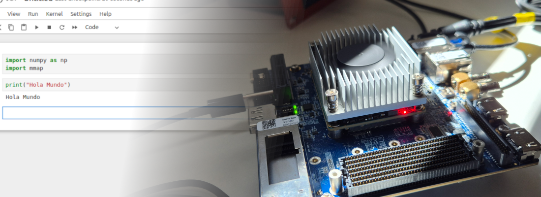
When the image download is complete, we will se the Linux boot. Remember that the processor is running at 100 MHz, so the speed is limited.

I know that running a Linux distribution in a 100 MHz processor could be not useful in some cases, but this is an example to show how far we can go with an FPGA. Also, if we don’t care about the speed, many times, using Linux to manage a high level communication interfaces can decrease the developing time. The power of this kind of system, are not the processor itself, but use the processor to manage the AXI interfaces in order to communicate with hardware accelerators implemented in the fabric.