Managing AXI4-Stream from MATLAB.
For developers who work with FPGA and digital signal processing, and for signal processing, I mean audio signals, video signals, and radio signals, … sure they have used the AXI4-Stream protocol. The AXI4-Stream protocol is used as a standard interface to connect components that want to exchange data. The interface can be used to connect a single master, which generates data, to a single slave, which receives data. In this blog we already used this protocol in the post where I talked about DMA, where the Zynq processing system sent and received data to the xFFT IP.
As we saw in this blog, MATLAB is a highly integrated tool with FPGAs through its HDL Coder and HDL Verifier packages, and since AXI4-Stream is a very common protocol, MATLAB has support for it, but unlike the AXI4-Lite protocol, to use the AXI4-Stream MATLAB uses IIO. On lasts posts I have talk about IIO, and how we can manage different peripherals from Linux. This case is very similar, we will have a Linux distribution on the PS, which will manage the AXI4-Stream interfaces, and will interchange data with MATLAB using LibIIO.
On this post, we will create an algorithm on Simulink, and then we are going to create an AXI4-Stream IP. The algorithm we are going to use to generate the AXI4-Stream IP will be a Goertzel filter. On this blog we saw how this filter works on this post, where we implemented this filter on the PS of a Zynq US+. On that occasion we had the limitation that, although this filter is an optimized solution for the FFT, for each sample we have to perform several multiplications to obtain the real and the imaginary part. This time the algorithm will be implemented on the PL, so the multiplications will be parallelized, and we will process the samples faster.
Remembering how the filter works, we start from the recursive equation of the DFT, which we can represent on the next diagram.

The equation of this feedback system can be written this way, where we obtain a complex equation (term W is complex). Resolving this equation for a number of samples, at the end of the series we will obtain the real and the imaginary part of the harmonic (k) selected.
\[H_k(z)=\frac{1}{1-W_N^{-k}z^{-1}}\cdot \frac{1-W_N^{-k}z^{-1}}{1-W_N^{-k}z^{-1}} = \frac{1-W_N^{-k}z^{-1}}{1-2cos(2 \pi k/N)z^{-1}+z^{-2}}\]On Simulink, the model of this filter can be drawn this way, where a result is a complex number.

Remember that the goal of this project is to generate a synthesizable HDL code, so the complex number must be converted to real numbers. To do that, we have to split the real and the imaginary sides using Euler’s formula, and the result will be the next.

Notice that, as the signal, we have generated is a real signal, only the real part of the result is added. At this point we have a diagram where we have 2 results that are real numbers (i is implicit on the imaginary result). Next will generate the HDL of this diagram, but first we need to define the width of the signals, and as we are working with a feedback system, it could be a bit confusing (we have to add some convert blocks because the input adder has the width of the input on one operand, and twice of the width on the other operand). To avoid this, we can let MATLAB do this job by using the equation instead of the diagram. If we remember the project where I designed an IIR filter on MATLAB and then generated the HDL code, this filter was be implemented with a biquad block, so we can use the biquad block, configuring the numerator and the denominator as the Goertzel filter.
To design the model, we will use a biquad filter where the coefficients will be configurable. We can do this configuring the source of the coefficients as inputs of the block. If we check the equation, we can see that only 2 coefficients are configurable (Wkn and 2cos(2pi/N)), and the rest are 1 or 0. Also, we will keep in mind that this algorithm behavior is like an integrator, so we need to perform a reset when the number of samples will be the configured. In our case, we will design a model which obtains the real part of the harmonic configured, and the number of samples will be 32. In order to reset the filter, I have used delay blocks with reset, so resetting the coefficients and the output for 2 samples, the entire filter will be reset. In this case I have used a 6 bits counter, and the system will remain in reset when the output of the counter will be greater than 31. Last, to make the system synchronous with the data valid signal of the AXI4-Stream protocol, all the algorithm will be inside of enabled subsystem. The algorithm model will look like the next.

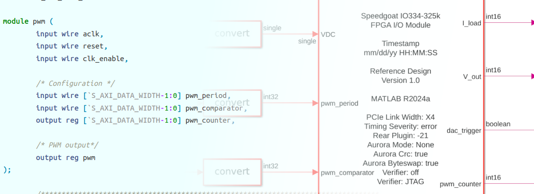
Regarding data formats, we have to keep in mind the values of the configuration variables, and the maximum value that the output will take. We can estimate the maximum value on simulation. In this case I will select a 32 bits format (this is been determined by the AXI4 protocol), with a decimal width of 16 bits.
On a top level, we have to define the AXI4-Stream signals, and the configuration parameters. Data valid signal will be used as enable signal to the algorithm. That means that the algorithm will process one sample at each rising edge of the data valid signal. The output data valid will be the same signal, so every 32 samples (34 countings the delays), the data on output_tdata port will be the value of the real part of the harmonic configured. The configuration of the algorithm will be done through AXI4-Lite.

On the top level of the model, we will find the output and the input ports.

Once the model is completed, we will use HDL Coder and Workflow Advisor to generate the HDL Code and the interface with MATLAB. When the Workflow Advisor windows will be opened, first we have to select as Target workflow IP Core Generation. Next, we have to select the board. On this step, MATLAB can select between several boards. In my case, I am going to use the Picozed 7015 board, which is not included on MATLAB by default. If this is your case, you can ask MathWorks HDL Application engineer for a support package for your board.

On the next point, we will select as Reference design Default system with AXI4-Stream interface (32 bits). Also, we will enable JTAG MATLAB as AXI Master to allow the configuration through AXI4-Lite. Also, on this window, you can modify the speed of the DMA. For this project I had some timing errors with frequencies above 100 MHz, so the final configuration I used was 100Mhz.

Last, to avoid timing errors, I selected as design frequency 25Mhz, which is enough for this project.

On the next point, we have to set the interfaces. At this point we will connect the AXI4-Stream signals to the corresponding ports, and the configuration parameters to the AXi4-Lite interface. The addresses of the AXI4-Lite will be filled automatically.

Finally, we will jump to point 3.2, set a name for the IP, and Run to the selected task to execute all the points.

On the next points, we will generate the Vivado project to build the system, and the Software interface will be generated. This point is important because later, we will use the software Simulink model to connect the FPGA to Simulink. Last, we will generate the bitstream.
To configure the FPGA, as I said before, we will have a Linux distribution running on the PS. That distribution has the corresponding libraries to configure the PL of the Zynq, so we can configure the FPGA through an Ethernet connection and the SSH protocol. In order to do that, we have to configure as programming method Download, configure the IP and the SSH user and password.

Once the device is configured, we have to open the software interface model generated before. This model has a block that is corresponding to the Zynq device, and it has inputs and output corresponding with the interface we defined before. MATLAB generates AXI4-Lite interfaces directly on the block, so we can connect the corresponding variables as constants to the configuration inputs of our model, in this case, these inputs are corresponding with the cosine variables, and the real part of the Wkn. On the other side, we have the inputs and output corresponding with the AXI4-Stream interface. MATLAB does not generate the interface for AXI4-Stream on the block, so we have to generate the interface using the blocks AXI4-Stream IIO Write to write data on the bus, and AXI4-Stream IIO Read to read data from the bus.

Once we have the interface model complete, we will package this model on a subsystem, and on the top model, we will connect the input data sources and the output data acquisitors. In this case, data to the AXI4-Stream interface will be generated on the workspace, this will allow us to compare the output of the algorithm of the FPGA and the theoretical output of the equation under the same conditions. As the input, output data will be sent to the workspace. Also, we need to connect the configuration variables to variables in our workspace, to do that we will use constant blocks with the value configured as existing variables. Before connecting data to the model, we have to perform a conversion in order to transform the data formats to the corresponding data formats, in this case, all the data interchanged with the algorithm is in I15Q16 format.

Once we have all the variables generated (the code to generate them is available on Github and FileExchange), we can execute our model, with a Stop time configured as infinite.

It is important to read the output data correctly on a scope, select Columns as channels on the bottom of the scope window.

If everything went ok, on the scope we will see something like this. We can see the output of the algorithm as an exponential increasing sine signal, where the final value is corresponding with the value of the real part of the harmonic configured.

In order to verify the correct behavior of the algorithm, I have compared the output of the MATLAB equation, and the output data captured through Simulink. In the first case, the harmonic configured (k) is equal to 2, and the output of both MATLAB and FPGA outputs is the same. The final value of the output data is corresponding with 16, that is corresponding with a cosine wave with an amplitude of 1 (16*2/N).

On the second case, k remains on 2, but the input signal is a 4th harmonic. We can see that the output is 0.

If we change the value of k to 4, we can see how the output of the algorithm is increased to 16.

In this project, we have seen how to design an AXI4-Stream IP with MATLAB and HDL Coder. This time we have performed a loop, where the input signal is generated on MATLAB, sent to the FPGA, and again read by MATLAB in order to capture the output of the algorithm. This method is very useful to verify the behavior of the filter, but there is not interaction with the real world. In the next project, we will use an external ADC to acquire data, and the output of the algorithm will be sent to MATLAB to see the filter’s behavior in real-time.
Files of this project can be found on File Exchange and Github.