Using a fixed-point solver on Speedgoat model.
In this blog, you have seen filters, regulators, and other kinds of DSP algorithms implemented in Verilog, and all of them have something in common, all of them were implemented using fixed-point precision. The reason for this is simple, I didn’t need more accuracy than 20 or 24 decimals bits can give me, and this is extensible to almost all the algorithms you will implement in your jobs. However, in articles where we used Matlab models, and especially when those models will be deployed on the Speedgoat target, I always used floating-point implementation. The reason for that is also very simple, Matlab only allows the implementation of Simscape solvers using floating-point, until now. The release r2024a brings us the possibility to use fixed-point implementations in the space-state representation of the model. As we will see, to do that we just need to set the corresponding precision in the Simscape HDL Workflow Advisor and let Simulink do all the job. In this article, we will test this new functionality, and verify the improvement. We can expect an improvement in the time step of the model, and also in the utilization of the FPGA.
The model we are going to use is a Boost converter. The next image shows the Simscape model. Unlike other articles, this time I used a MOSFET. This adds to the model some extra parameters like the diode forward voltage or the gate voltage threshold and is this parameter that we need to change. This voltage, by default, is two volts, so if you are using a PWM signal with a value of ‘1’ for the activation, this MOSFET will never turn on. To make it work correctly, you can change the gate voltage threshold to 0.5, so it will work with a value of one. The rest of the model is the same as we made in this article.
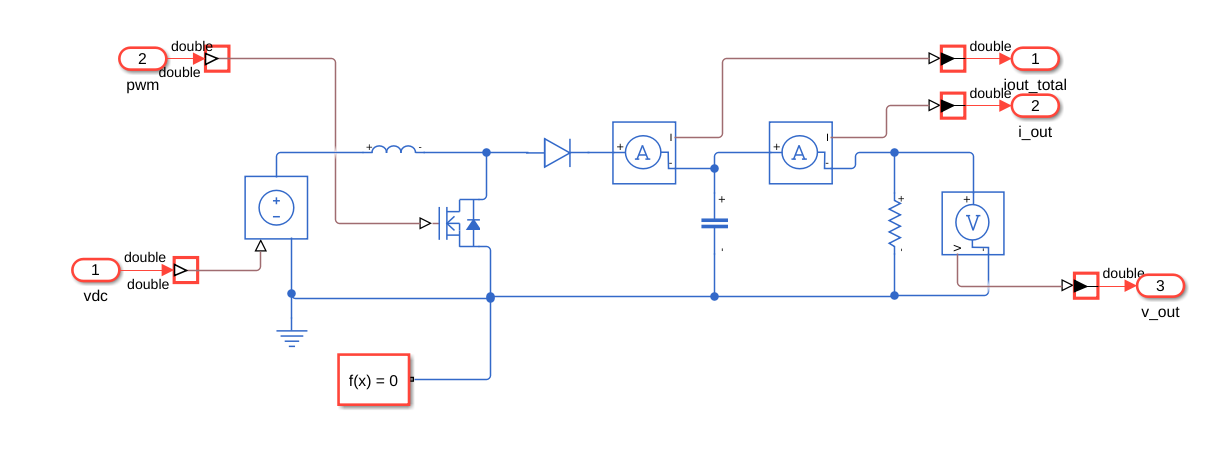
The FPGA model will contain the Simscape converter model, and all the circuits to adapt the measures to the Speedgoat DAC. Also, we need to add the Signal Specification blocks to set the data type of the inputs and the outputs of the converter model. The FPGA model this time also includes the PWM generation. This way I can generate and run the model without external elements.

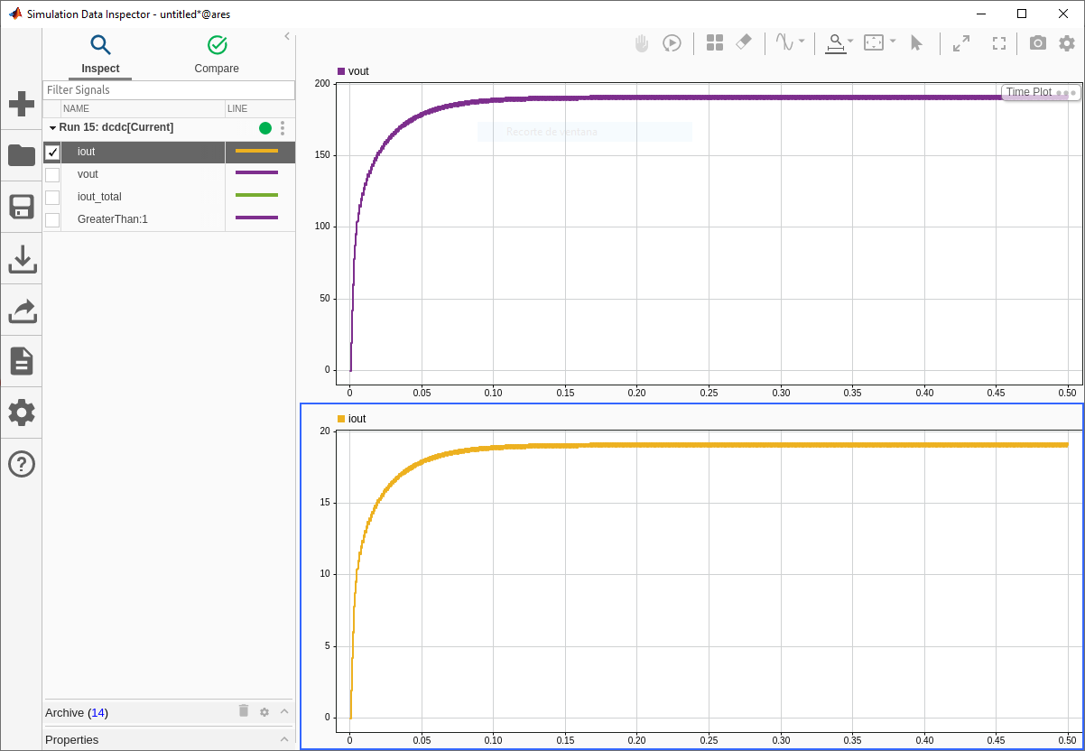
In order to check that the model is correct, we can simulate the model, and verify that the output voltage is correct.
At this point, we have our model, the next step is to translate the Simscape model into a Space-State model. To launch the Simscape HDL Workflow Advisor, I have developed the next script. It is pretty similar to the script used in other articles but, this time, I have added the configuration of the parameter MaxNonlinIter (Max Number of Iterations), and the Oversampling. The number of iterations needed by the solver to solve the converter for a circuit like this will be is the most of the cases two. The oversampling factor is related, when we are implementing the solver using single precision, to the floating-point operators latency. In this case I have used an oversampling factor of 50, which means that the model will receive the FPGA clock frequency divided by 50.
open_system('dcdc');

set_param(['dcdc/FPGA/boost/Solver Configuration'],'DoFixedCost','on')

set_param('dcdc', 'ProdHWDeviceType', 'ASIC/FPGA->ASIC/FPGA')

% Set number of solver iterations
set_param('dcdc/FPGA/boost/Solver Configuration','MaxNonlinIter','2')

% set oversamplig factor
hdlset_param('dcdc','Oversampling',50)

% set general setup
hdlsetup("dcdc")

% Launch SS HDL advisor
sschdladvisor('dcdc')
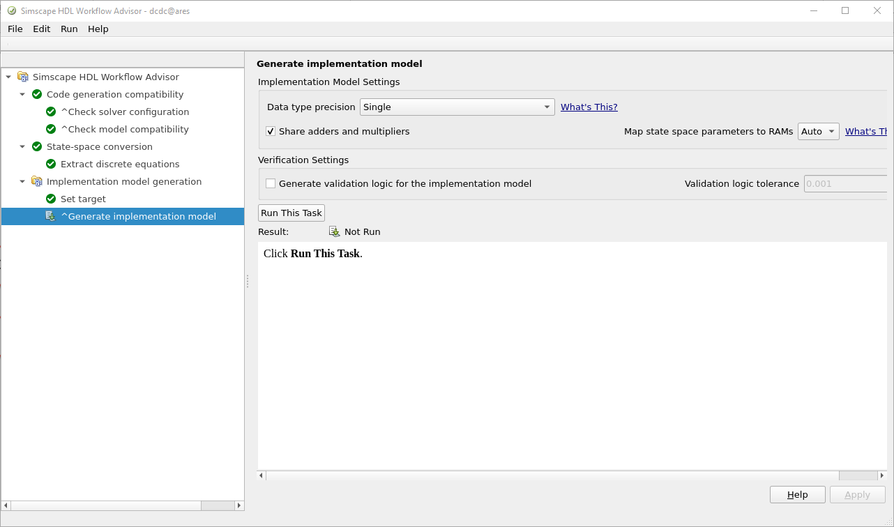
In the last step of the Simscape HDL Workflow Advisor, we can select the data type precision. In this case we are going to select single.
Once the space-state model is generated, we can launch the HDL Workflow Advisor to generate the RTL code that will be deployed in the Speedgoat target. The next script launch the HDL Workflow Advisor, and change all the Signal Specifications blocks to single.
hdlsetuptoolpath('ToolName','Xilinx Vivado','ToolPath','/mnt/data/amd/Vivado/2023.1/bin/vivado');

open('./sschdl/dcdc/gmStateSpaceHDL_dcdc.slx')

set_param('gmStateSpaceHDL_dcdc', 'SimulationCommand', 'Update')

set_param('gmStateSpaceHDL_dcdc/FPGA/Signal Specification','OutDataTypeStr','single');
set_param('gmStateSpaceHDL_dcdc/FPGA/Signal Specification1','OutDataTypeStr','single');
set_param('gmStateSpaceHDL_dcdc/FPGA/Signal Specification2','OutDataTypeStr','single');
set_param('gmStateSpaceHDL_dcdc/FPGA/Signal Specification3','OutDataTypeStr','single');
set_param('gmStateSpaceHDL_dcdc/FPGA/Signal Specification4','OutDataTypeStr','single');

hdlsetup('gmStateSpaceHDL_dcdc')

hdladvisor('gmStateSpaceHDL_dcdc/FPGA')
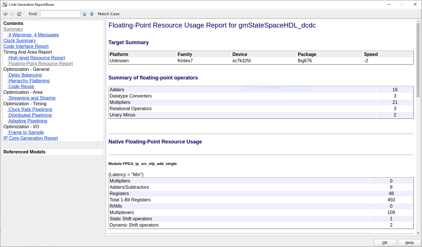
In step three, when the HDL code is generated, in the report we can see that the model indeed uses floating-point operators. We can also check the amount of floating-point resources used like multiplicators, additions, or relational operators.
I the step four, we will create the project and implement the design on Vivado. Once the implementation is finished, we can open Vivado from the Matlab command window executing the command
!vivado
Now, we can navigate to hdl_prj_single > vivado_ip_prj, and open the project to check the utilization.
For the single precision model, we can see the utilization of the device.
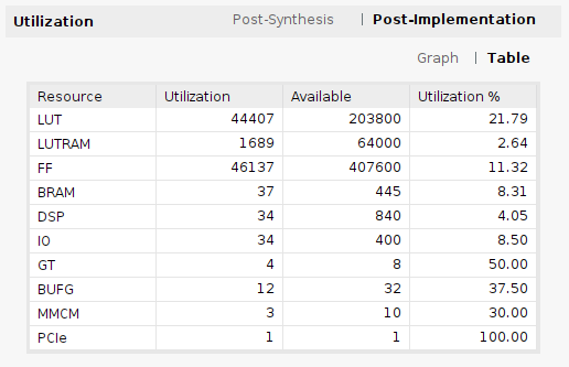
Notice that the Speedgoat FPGA does not have just the converter model, but it also contains all the logic related to the PCI, DAC, and digital IOs… To check the utilization of the converter, we need to open the Utilization report and check the utilization per module.

For a single precision implementation, we can see that the model uses 11062 LUTs and 33 DSP blocks. Regarding the time step of the model, it can be calculated following the next equation:
\[fs = \frac{F_{CLK}}{N_{iterations} \cdot OversamplingFactor}\] \[ts = \frac{1}{fs}\]So in this case
\[fs = \frac{100e6}{2 \cdot 50}\] \[ts = 1us\]Now, we will implement the same model, but this time using a fixed-point precision.
open_system('dcdc');

set_param(['dcdc/FPGA/boost/Solver Configuration'],'DoFixedCost','on')

set_param('dcdc', 'ProdHWDeviceType', 'ASIC/FPGA->ASIC/FPGA')

% Set number of solver iterations
set_param('dcdc/FPGA/boost/Solver Configuration','MaxNonlinIter','2')

% set oversamplig factor
hdlset_param('dcdc','Oversampling',1)

% set general setup
hdlsetup("dcdc")

% Launch SS HDL advisor
sschdladvisor('dcdc')
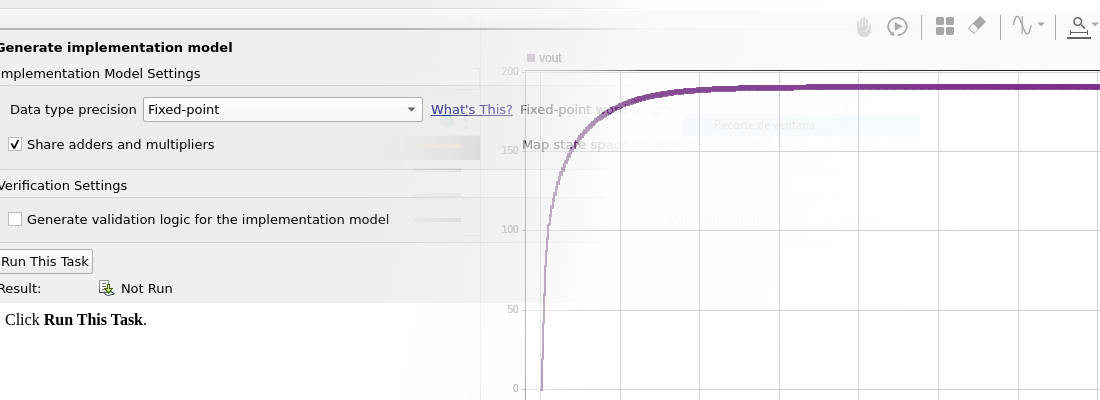
In the last step, we have to select in this case the fixed-point precision. Doing this will allow us to select the data width. When we use a fixed-point precision, we need to define both the data width, and the decimal width, however, Matlab only allows us to select the data width, and the decimal width will be configured automatically according to the precision needed by the solver.
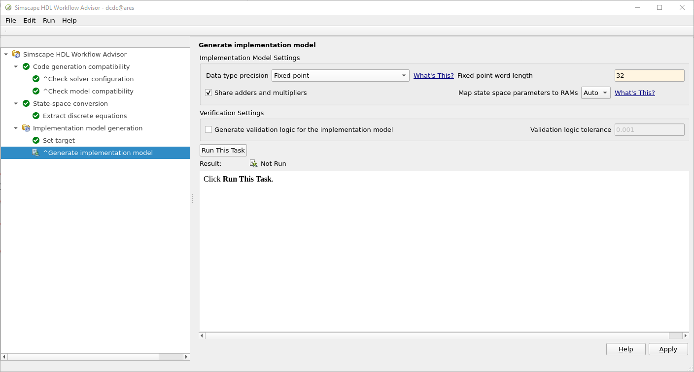
This time, the generation of the model will take more time than the single precision implementation. Once the model is generated, we can open the gmStateSpaceHDL_dcdc_fixpt.slx, located at ./sschdl/dcdc/. Here we can see how the converter generated model uses the data type sfix32_En21, which means 32-bit data width, and 21-bit for the decimal part.

Now, we can launch the HDL Workflow Advisor, but before, we need to change the Signal Specification blocks from double to sfix32_En21. This is very important because, in case we leave them configured as single or double precision, the model will use floating-point operators, even if the solver is implemented in fixed-point, so in this case, the oversampling factor will be misconfigured.
hdlsetuptoolpath('ToolName','Xilinx Vivado','ToolPath','/mnt/data/amd/Vivado/2023.1/bin/vivado');

open('./sschdl/dcdc/gmStateSpaceHDL_dcdc_fixpt.slx')

set_param('gmStateSpaceHDL_dcdc_fixpt', 'SimulationCommand', 'Update')

% change the fixed-point precission according the solver precission!
set_param('gmStateSpaceHDL_dcdc_fixpt/FPGA/Signal Specification','OutDataTypeStr','fixdt(1,32,21)');
set_param('gmStateSpaceHDL_dcdc_fixpt/FPGA/Signal Specification1','OutDataTypeStr','fixdt(1,32,21)');
set_param('gmStateSpaceHDL_dcdc_fixpt/FPGA/Signal Specification2','OutDataTypeStr','fixdt(1,32,21)');
set_param('gmStateSpaceHDL_dcdc_fixpt/FPGA/Signal Specification3','OutDataTypeStr','fixdt(1,32,21)');
set_param('gmStateSpaceHDL_dcdc_fixpt/FPGA/Signal Specification4','OutDataTypeStr','fixdt(1,32,21)');

hdlsetup('gmStateSpaceHDL_dcdc_fixpt')

hdladvisor('gmStateSpaceHDL_dcdc_fixpt/FPGA')
Here, the steps are the same we followed for the single precision with some little changes. In order to keep both projects, I changed the name of the HDL folder, adding the suffix _fixpt
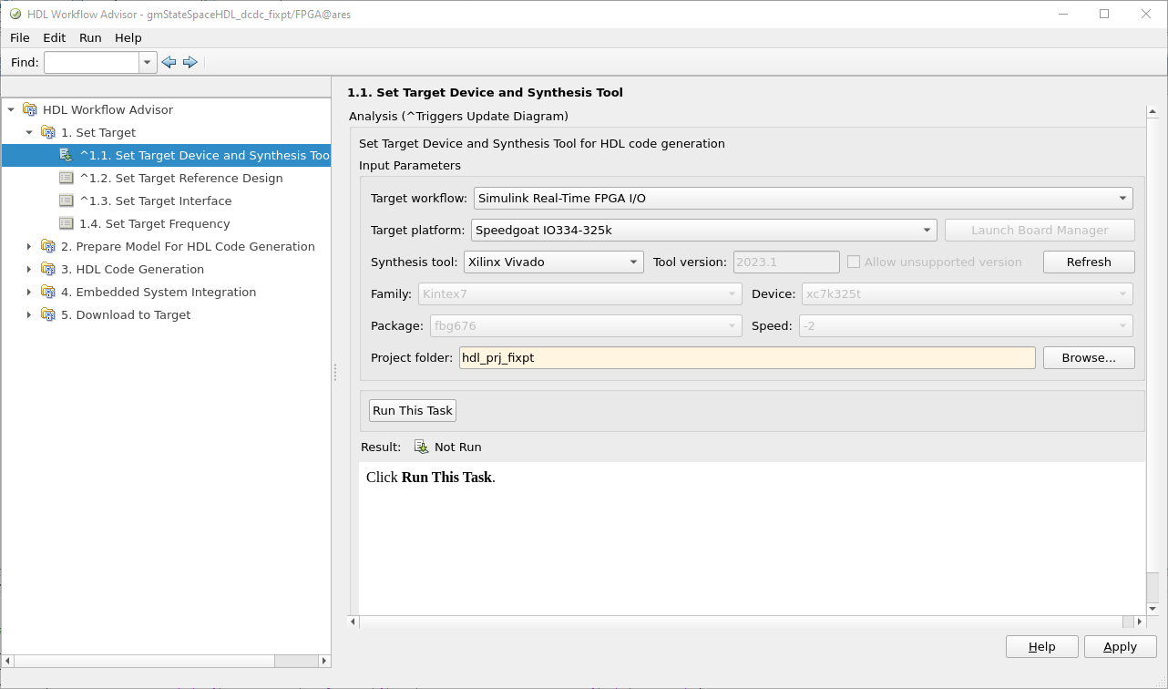
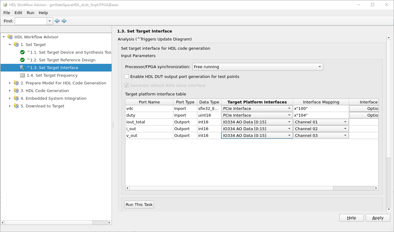
The interface of the model can be configured as follows.
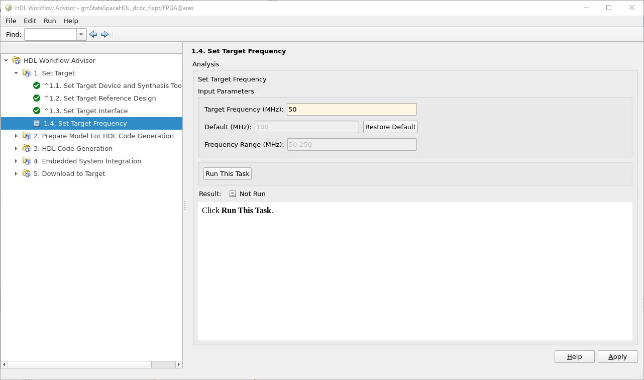
Since we reduced the oversampling factor, we can reduce the clock of the FPGA. In this case I will use a clock of 50 MHz.
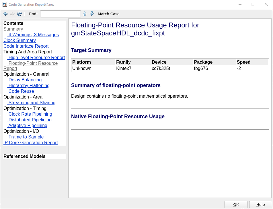
When the HDL code is generated, we can see in the report that, indeed, there is no floating-point operations in the model, so all the model is implemented using fixed-point.
Once the model is implemented, we can open Vivado and check the utilization. For this model, we can see how the entire design uses the 17% of the FPGA, a 4% less than the single precision implementation.
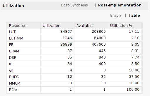
Opening the utilization report, we can see the utilization of the IP generated, which is in this case 1522 LUTs, a 10% of the single precision implementation. However, the use of DSP blocks has been increased to 64.

Regarding the time step of the model, reducing the oversampling will give us a boost in the model execution performance, reducing the time step to 40 ns.
\[fs = \frac{50e6}{2 \cdot 1}\] \[ts = 40ns\]In general, when we work with real-time simulation targets, we need both accuracy and small time steps, and both can be achieved using fixed-point implementations, especially in small and medium-sized models, where FPGA utilization is not high. For other cases, where fixed-point accuracy is not sufficient, we can sacrifice a little time step to achieve high accuracy. In any case, in this article, we have seen how easy it is to switch between single precision to fixed-point precision, making testing the fixed-point precision model and later, if we need more precision, upgrading to a single-precision model, a good option.


