Creating a custom PolarFire SoC design.
 Icicle kit
FPGA manufacturers are determined to show us how their devices can do very difficult things like process video, detect in that video who is wearing a mask and who is not, detect if the people is happy or not… all of this while a led is blinking. This make that the information we can find are related to those kind of projects. Nowadays is difficult to find a project provided by the manufacturers showing only how to run for the first time its device, I am afraid that is easier today to find how to process video, than a complete tutorial to learn how blink a led. Even the most basic examples are plenty of code that is unnecessary for a basic application, and usually they forgot some steps that, for your project, are the difference between working and do not working. During my years at the college, when I started to program in C, my teacher always said us that the most difficult part of a program is to face the blank sheet. In this blog I try to show you how, from the blank sheet, we can create some interesting projects, or at least, how to create a project that makes the device do things. And this is exactly what we are going to do in this post, start-up the Microchip PolarFire SoC and the Icicle kit from a blank sheet.
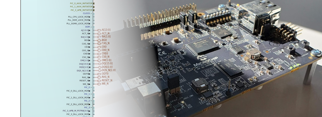
The first time that I saw the PolarFire SoC, with its five RISC-V core, I thought that it will be difficult to make all of them working. Also, the reference design that they provide you is a huge SmartDesign where it difficult to find the different peripherals, and how they are connected. Also, one of the examples provided, where you only have to add a new core in the fabric, and connect it to the MSS, it use the entire SmartDesign, when only a FIC bus is used… As I said, in this post I want to show you how you can create a very basic design to run in the Microchip’s Icicle Kit, and you will see how it is easier than it could seem. The project will use two of the five cores, and we will see how we can interact make them interact. In the next image You can see the structure of a PolarFire SoC. We have five RISCV cores in total, one E51 core to use it as monitor core, and four U54 core to run the application. All cores can run up to 667 MHz, and all of them have access to the peripherals and memory.

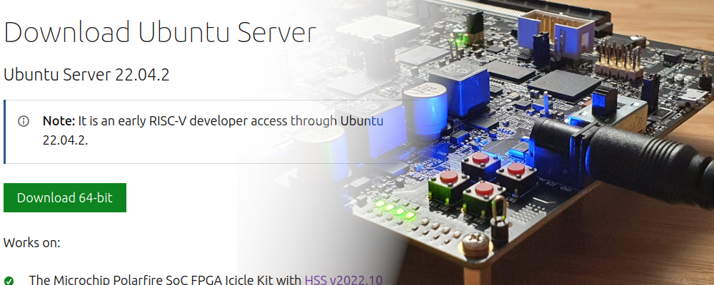
First of all, we are going to create a new project in Libero SOC, for the part of the Icicle kit, the MPFS250T.

Then we have to select the core voltage and the IO voltage.

Once the project is finished, since the project is based on the processor, we need to create an SmartDesign.

At this point, you will notice that in the catalog of Libero, we only have soft-cores like the Mi-V RISC-V processors, although the part we are selected has a hardcore processor, it does not appear in the catalog. This is because Libero uses an external application to create and configure the MSS of the PolarFire SoC. Then, that component will be added to the SmartDesign. The application itself is named PolarFire SoC MSS Configurator, and it is installed with Libero SOC 2022. To open the application in LInux, I have used the next command.
pablo@friday:~$ /media/pablo/ext_ssd0/Libero_SoC_v2022.2/Libero/bin64/pfsoc_mss
Once the application is opened, we need to create a new project, configure a name for the configuration, and to make the confiGuration easier, I have use a board preset, that will create a configuration for the selected board, then we can modify that configuration in order to customize it. In this case, I have used the board preset of the icicle kit, in its bare Metal configuration.

Now we can navigate between the different tabs in order to enable or disable different peripherals or parts of the PolarFire SoC. Since I am going to create a basic project, I have configured as Unused most of the peripherals that are enabled by default. I have configure only the UART from 0 to 3, since they are connected to the same chip, and also the GPIO 2, that is the one connected to the fabric, only the pins 0 to 3, in order to connect them to the LED of the board.

The next two tabs contain the memory configuration, which will remain its default configuration since it depends of the hardware of the board. For the FIC interfaces, I have disabled all of them.

Finally, in the last tab, I have disabled the interrupts port input.

Now we have to click over the cylinder in the top of the window in order to generate the outputs. It will ask us for a directory since it will generate a couple of files with different extensions.
pablo@friday:~/workspace/microchip/06_basic_icicle/mss$ tree .
.
├── custom_icicle_kit.cfg
├── custom_icicle_kit.cxz
├── custom_icicle_kit_mss_cfg.xml
└── custom_icicle_kit_Report.html
.cfg: Stores the configuration of the MSS. This file can be opened later with PFSOC MSS Configurator in order to modify it..cxz: Is the file that will be imported in Libero SOC in order to generate the MSS component..xml: This file is used in SoftConsole in order to generate the hardware configuration header..html: This file contains information about the MSS generated. useful to add to the documentation of the project.
Opening again Libero SOC, in the Design flow, we have to import the MSS configuration, the .cxz file. Then we will see a new component, the MSS that we have to instantiate in the SmartDesign generated before.

When the component is instantiated in the SmartDesign, we only have to connect externally the GPIO,by right click and promoting the pin to the top level, the ports reset input, and the UART. In order to use the Icicle Kit, we can download its constraints file from the PolarFire SoC Github. The constraints are located in the script_support folder. The rest of the outputs have to be defined as unused in order to avoid warnings.

At this point we have the hardware design complete, we only have to generate the bitstream and program de device.
Once the PolarFire SoC is configured, we can close Libero SoC and open SoftConsole. To make the process of the project creation easy, I have imported an example project from the PolarFire SoC Bare Metal Examples repository. In this repository, there are many projects, the project I have used is /driver-examples/mss/mss-mmuart/mpfs-mmuart-interrupt/. This project uses the E51 core, and two of the U54 cores. You have all the information about this project in the readme file, but we are going to change the project to make it easy, so to follow my steps, it is not relevant. When we have the project copied locally, we can import the project to SoftConsole as usual.
When the project is imported, we will have the next structure.
pablo@friday:/media/pablo/ext_ssd0/sc_workspace/mpfs-mmuart-interrupt$ tree -L 2 .
.
├── mpfs-mmuart-interrupt hw all-harts attach.launch
├── mpfs-mmuart-interrupt hw all-harts debug.launch
├── mpfs-mmuart-interrupt renode all-harts debug.launch
├── mpfs-mmuart-interrupt renode all-harts start-platform-and-debug.launch
├── README.md
└── src
    ├── application
    ├── boards
    └── platform
You also can have a folder names LIM-debug with the generated outputs of a previous compilation, but this folder will be filled before we compile our new project. In the default project we will have some .launch files, with different debug configurations, and a src folder, with all the code of the project. Inside thr src folder, we will have the next structure.
pablo@friday:/media/pablo/ext_ssd0/sc_workspace/mpfs-mmuart-interrupt$ tree -L 2 ./src
./src
├── application
│   ├── hart0
│   ├── hart1
│   ├── hart2
│   ├── hart3
│   ├── hart4
│   └── inc
├── boards
│   └── icicle-kit-es
└── platform
    ├── drivers
    ├── hal
    ├── mpfs_hal
    ├── platform_config_reference
    └── soc_config_generator
In the application folder we will have different folders with the program that will run each core. Also we have a platform folder with all the drivers for the hardware abstraction layer (hal), the peripheral drivers… and finally we have a boards folder with the information about the hardware we are going to use. Inside this folder we have a simple structure of three folders, fpga_design, fpga_design_config and platform_config.
pablo@friday:/media/pablo/ext_ssd0/sc_workspace/mpfs-mmuart-interrupt$ tree -L 3 ./src/boards/
./src/boards/
└── icicle-kit-es
    ├── fpga_design
    │   └── design_description
    ├── fpga_design_config
    │   ├── clocks
    │   ├── ddr
    │   ├── fpga_design_config.h
    │   ├── general
    │   ├── io
    │   ├── memory_map
    │   └── sgmii
    └── platform_config
        └── mpfs_hal_config
Inside fpga_design/design_description is where we have to copy the xml file generated by the PolarFire SoC MSS Configurator. IN the example project, in this folder we will have the xml corresponding with the default configuration, so we will need to replace this by our new file with a simple configuration. Also, if you want, or need, to keep the default configuration, you can create a new structure under boards folder. In this case, you wll have to navigate to the properties of the project, and modify the include folders under the configuration C/C++ Build > Settings > Includes. If you replace the file, you don’t have to do nothing more than copy the new xml and delete the older one.
OK, we have copied our new configuration but, how does SoftConsole to take the new configuration and apply it?, well, the truth is that SoftConsole does nothing with the configuration, is an external Python script who reads the xml, and generate all the needed header files according the hardware confgiuration passed. The script is the mpfs_configuration_generator.py, and you can find it in this repository but, since we are using an example project, the script is already in the project, so we don’t have to download the script. Now, have we to execute the script?, no, we don’t have to execute the script, again, since we are using an example project, the project is configured to execute the script just before start the build process.

If you have created a new folder under boards, you will have to modify the call of the script to replace the folder where is the xml file by the new one created.
At this point we have our project ready to be built and execute it, but before, we are going to modify a little bit the code. First of all, since we are using only the E51 core, and one of the U54 cores, we can modify the file mss_sw_config.h under boards/icicle-kit-es/platform_config/mpfs_hal_config to use only the cores 0 and 1.
#ifndef MPFS_HAL_FIRST_HART
#define MPFS_HAL_FIRST_HART  0
#endif

#ifndef MPFS_HAL_LAST_HART
#define MPFS_HAL_LAST_HART   1
#endif
Then we have to delete all the example code of the U54_2 core, so we have to copy the code of the U54_3 core to the U54_2 core. Making this, we have the core two disabled. I have changed the references to the hart 3 by hart 2 for be consistent. The code of the hart 2 is the next.
#include <stdio.h>
#include <string.h>
#include "mpfs_hal/mss_hal.h"
#include "drivers/mss/mss_mmuart/mss_uart.h"

volatile uint32_t count_sw_ints_h2 = 0U;

/* Main function for the hart3(U54_2 processor).
 * Application code running on hart2 is placed here
 *
 * The hart3 goes into WFI. hart0 brings it out of WFI when it raises the first
 * Software interrupt to this hart.
 */
void u54_2(void)
{
    uint64_t hartid = read_csr(mhartid);
    volatile uint32_t icount = 0U;

    /* Clear pending software interrupt in case there was any.
       Enable only the software interrupt so that the E51 core can bring this
       core out of WFI by raising a software interrupt. */

    clear_soft_interrupt();
    set_csr(mie, MIP_MSIP);

    /* Put this hart in WFI. */
    do
    {
        __asm("wfi");
    }while(0 == (read_csr(mip) & MIP_MSIP));

    /* The hart is now out of WFI, clear the SW interrupt. Here onwards the
     * application can enable and use any interrupts as required */

    clear_soft_interrupt();

    __enable_irq();


    while(1U)
    {
        icount++;

        if(0x100000U == icount)
        {
            icount = 0U;
        }
    }

  /* Never return */
}

/* hart2 software interrupt handler */
void Software_h2_IRQHandler(void)
{
    uint64_t hart_id = read_csr(mhartid);
    count_sw_ints_h2++;
}
Then, we are going to modify the code. The code that I have implemented run the E51 and send by UART an string asking the user to press the key ‘1’ in order to activate the U54_1 core. Then, when the key ‘1’ is pressed, the U54_1 core sends an string to indicate that it has been received the order to start. The E51 core will use the MMUART0, and the U54_1 core will use the MMUART1. The code for the E51 core is the next.
#include <stdio.h>
#include <string.h>
#include "mpfs_hal/mss_hal.h"
#include "drivers/mss/mss_mmuart/mss_uart.h"
volatile uint32_t count_sw_ints_h0 = 0U;

#define RX_BUFF_SIZE    16U
uint8_t g_rx_buff0[RX_BUFF_SIZE] = {0};
uint8_t rx_size0 = 0U;

const uint8_t e51_message[] = "Hello world from E51! \n\rPress '1' to wake up the U54_1\n\r";
const uint8_t e51_message_good[] = "EI U54_1! Wake Up\n\r";
const uint8_t e51_message_wrong[] = "I said '1', not any key!\n\r";

void e51(void)
{
    uint64_t hartid = read_csr(mhartid);

    /* enable MMUART 0 */
    (void) mss_config_clk_rst(MSS_PERIPH_MMUART0, (uint8_t) 1, PERIPHERAL_ON);

    /* Init MMUART 0 */
    MSS_UART_init(&g_mss_uart0_lo,
    MSS_UART_115200_BAUD,
    MSS_UART_DATA_8_BITS | MSS_UART_NO_PARITY | MSS_UART_ONE_STOP_BIT);

    /* Send Message on uart0 */
    MSS_UART_polled_tx(&g_mss_uart0_lo, e51_message,
            sizeof(e51_message));

    /* Clear pending software interrupt in case there was any. */
    clear_soft_interrupt();
    set_csr(mie, MIP_MSIP);

    while (1U)
    {
        /* Check for any message in MMUART0  */
        rx_size0 = MSS_UART_get_rx(&g_mss_uart0_lo, g_rx_buff0, sizeof(g_rx_buff0));
        if(rx_size0 > 0)
        {
            switch (g_rx_buff0[0u])
            {
            case '1':
                /* Raise software interrupt to wake up hart 1 */
                raise_soft_interrupt(1U);
                MSS_UART_polled_tx(&g_mss_uart0_lo, e51_message_good,
                            sizeof(e51_message_good));
                __enable_irq();
                break;
            default:
                MSS_UART_polled_tx(&g_mss_uart0_lo, e51_message_wrong,
                        sizeof(e51_message_wrong));
                break;
            }
        }
    }

}

/* hart0 software interrupt handler */
void Software_h0_IRQHandler(void)
{
    uint64_t hart_id = read_csr(mhartid);
    count_sw_ints_h0++;
}
And, the code for the U54_1 core is the next.
#include <stdio.h>
#include <string.h>
#include "mpfs_hal/mss_hal.h"
#include "drivers/mss/mss_mmuart/mss_uart.h"
#include "inc/common.h"

volatile uint32_t count_sw_ints_h1 = 0U;
const uint8_t wake_message1[] = "Here U54_1! I am awake!\n\r";

#define RX_BUFF_SIZE    16U
uint8_t g_rx_buff1[RX_BUFF_SIZE] = { 0 };

void u54_1(void)
{
    uint64_t mcycle_start = 0U;
    uint64_t mcycle_end = 0U;
    uint64_t delta_mcycle = 0U;
    uint64_t hartid = read_csr(mhartid);


    clear_soft_interrupt();
    set_csr(mie, MIP_MSIP);

    /* Put this hart in WFI. */
    do
    {
        __asm("wfi");
    }while(0 == (read_csr(mip) & MIP_MSIP));

    /* The hart is now out of WFI, clear the SW interrupt. Here onwards the
     * application can enable and use any interrupts as required */
    clear_soft_interrupt();

    /* interrupt received */
    __enable_irq();

    /* enable MMUART 1 */
    (void) mss_config_clk_rst(MSS_PERIPH_MMUART1, (uint8_t) 1, PERIPHERAL_ON);

    /* Init MMUART 1 */
    MSS_UART_init(&g_mss_uart1_lo,
    MSS_UART_115200_BAUD,
    MSS_UART_DATA_8_BITS | MSS_UART_NO_PARITY | MSS_UART_ONE_STOP_BIT);

    /* Send wake message */
    MSS_UART_polled_tx(&g_mss_uart1_lo, wake_message1,
            strlen(wake_message1));

    /* infinite loop */
    while(1);
}

/* hart1 Software interrupt handler */

void Software_h1_IRQHandler(void)
{
    uint64_t hart_id = read_csr(mhartid);
    count_sw_ints_h1++;
}
Notice that the U54_1 core waits until the E51 core raise a software interrupt in the U54_1 core, then this core configure the UART peripheral and run its code. The result is the next.

Ok! Looks easy, isn’t it? well, in my trip to this Putty outputs, I have had some situations. I use Ubuntu 20.04, so I don’t know if using Windows or other Linux distribution it will happen. The first one, I could not get SoftConsole to detect the embedded FlashPro6 of the Icicle kit, although Libero SOC does without any issue. I have had to execute SoftConsole as sudo to be able to program the board. And also, I lose some time because SoftConsole could not halt the E51 core, the solution was, once the PolarFire SoC is configured, to press the SW4 in order to make a reset to the MSS. That done, everything works fine.
Hope you will be able to follow all my steps, and have your icicle kit running with your own design. Adding a FIC interface will open the possibilities since we can use the fabric to create some acceleration kernels or peripherals in order to expand the capabilities of the board.