F4PGA and Project XRAY.
 Arty A7
When I think about Open Source, the first that comes to my mind is GNU/Linux. This operating system was developed by Linus Torvalds and Richard Stallman in the early 90’s, then all the code was released to the community. Now, this first operating system has grown, and we can find many different operating systems based on the kernel GNU/Linux. As for open source hardware, Arduino arrived in 2005, and it was a revolution. Today, we can find hundreds of boards compatible with Arduino and the Arduino IDE, with many different purposes. So, what about the FPGA?
Fortunately. the Open Source fever, many years later, has arrived to the FPGA field. Now we can find open source boards like the Opal kelly Brain-1 or the Trenz S7 Mini. If we talk about the development environments, the things turns a little bit dark. We have some synthesis tools like Icarus for Verilog, or GHDL if you use VHDL. These synthesis tools aims to translate the code into a digital generic circuit. Once we have this generic circuit, we have to translate it to fit in the FPGA. That means a very deep knowledge about the internal architecture of the FPGA, the resources it have, and the most important, the way to configure those resources to do what we need. Unfortunately, FPGA vendors has hide this information outside its doors, so, here again, the community, has researched using reverse engineering in order to decode from the bitstream, the way that all the elements of an FPGA has configured, here is where F4PGA, before known as Symbiflow, can helps us.
As we can read in the F4PGA web page
F4PGA is a fully open source toolchain for the development of FPGAs of multiple vendors. Currently, it targets the Xilinx 7-Series, Lattice iCE40, Lattice ECP5 FPGAs, QuickLogic EOS S3 and is gradually being expanded to provide a comprehensive end-to-end FPGA synthesis flow.
The idea behind F4PGA is to be a place where we can find different open source tools to implement FPGA designs, but not only that, also a place where find documentation about the internal architecture of the FPGA, the way how the different logic cells are configured or the format of its bitstream. Inside F4PGA there are 3 different projects:
- Project Icestorm: Documentation about the Lattice iCE40 FPGA.
- Project Trellis: Documentation about Latice ECP5.
- Project X-Ray: Documentation about Xilinx 7Series.
In addition to the documentation, F4PGA also provide the tools to implement FPGA designs using open source tools. In the case of FPGA of the Xilinx 7 Series, for the synthesis, F4PGA uses Yosys, for the place & route uses VTR from the Toronto University, and finally, to send the design to the FPGA, F4PGA uses OpenFPGAloader. Like Litex, F4PGA is based on Python scripts that calls the different tools, so we can use a docker container to deploy a complete FPGA implementation environment, what open the door to deploy this environment in the cloud. A this point we can ask, what is a container? , and whats the difference with a Virtual Machine (VM)?. Essentially, a VM implements all layers of the operating system, however, containers runs over the host operating system, with the highest layers of the container operating system. That is the reason because there are some host operating systems that are unable to run some other operating systems in a container. Despite of this difference, for the major operating systems we are not going to have problems. Also, the size of a container, since it only implement some layers of the operating system, is considerably smallest then a VM.
For this post, we are going to use an Ubuntu container, where we are going to run F4PGA. First of all we need install docker and create a container with all the tools needed by F4PGA in order to implement designs in 7Series FPGA.
Once docker is installed, we have to create a new container with the official ubuntu image. In this container, we have to create a shared folder with the host, in order to copy the source files.
pablo@miercoles:~/f4pga$ docker run -it -d -v ~/f4pga_container:/shared --name f4pga_container ubuntu
Once the container is created, we can check it with the command docker ps
pablo@miercoles:~/f4pga$ docker ps
CONTAINER ID   IMAGE     COMMAND   CREATED        STATUS         PORTS     NAMES
4abfb98035f7   ubuntu    "bash"    5 minutes ago  Up 5 seconds             f4pga_container
Now we can start the docker container.
pablo@miercoles:~/f4pga$ docker start f4pga_container
Next, we have to enter in the container using bash. This will allow us to execute commands inside a container.
pablo@miercoles:~/f4pga$ docker exec -it f4pga_container /bin/bash
Once inside the container, we have to navigate to the shared folder, which is the shared folder with the host.
root@4abfb98035f7:/# cd shared
Now, we have to follow the instructions you will find in the Getting F4PGA page. First of all, update the app repository, and install git, wget and xz-utils
root@4abfb98035f7:/# apt update -y
root@4abfb98035f7:/shared#  apt install -y git wget xz-utils
Now we have to clone the git repository of the f4pga_examples.
root@4abfb98035f7:/shared# git clone https://github.com/chipsalliance/f4pga-examples
root@4abfb98035f7:/shared# cd f4pga-examples
Then, download the package manager Conda.
root@4abfb98035f7:/shared# wget https://repo.continuum.io/miniconda/Miniconda3-latest-Linux-x86_64.sh -O conda_installer.sh
Now we have to declare some environment variables.
root@4abfb98035f7:/shared# export F4PGA_INSTALL_DIR=~/opt/f4pga
root@4abfb98035f7:/shared# export FPGA_FAM=xc7
And finally all the needed packages·
root@4abfb98035f7:/shared# bash conda_installer.sh -u -b -p $F4PGA_INSTALL_DIR/$FPGA_FAM/conda;
root@4abfb98035f7:/shared# source "$F4PGA_INSTALL_DIR/$FPGA_FAM/conda/etc/profile.d/conda.sh";
root@4abfb98035f7:/shared# conda env create -f $FPGA_FAM/environment.yml
Now we have to install the files corresponding with the families we want to implement.
root@4abfb98035f7:/shared# export F4PGA_PACKAGES='install-xc7 xc7a50t_test xc7a100t_test xc7a200t_test xc7z010_test'
root@4abfb98035f7:/shared# mkdir -p $F4PGA_INSTALL_DIR/$FPGA_FAM

F4PGA_TIMESTAMP='20220803-160711'
F4PGA_HASH='df6d9e5'

for PKG in $F4PGA_PACKAGES; do
  wget -qO- https://storage.googleapis.com/symbiflow-arch-defs/artifacts/prod/foss-fpga-tools/symbiflow-arch-defs/continuous/install/${F4PGA_TIMESTAMP}/symbiflow-arch-defs-${PKG}-${F4PGA_HASH}.tar.xz | tar -xJC $F4PGA_INSTALL_DIR/${FPGA_FAM}
done
At ths point we have all installed.
In order to verify that all works fine, F4PGA is installed with some examples. The examples are in the /xc7 folder. To implement one of the examples, from the f4pga-examples folder, we have to call the make command. If we start from a closed container, or from a new terminal session, before implement the design, we need to export the corresponding environment variables. Once all the variables are declared, from the /xc7 folder, we have to execute the command TARGET="arty_35" make -C <Project Folder>. In this case, we are going to implement the example called counter test. The commands are as follows.
root@4abfb98035f7:/shared/f4pga-examples# export F4PGA_INSTALL_DIR=~/opt/f4pga
root@4abfb98035f7:/shared/f4pga-examples# export FPGA_FAM="xc7"
root@4abfb98035f7:/shared/f4pga-examples# source "$F4PGA_INSTALL_DIR/$FPGA_FAM/conda/etc/profile.d/conda.sh"
root@4abfb98035f7:/shared/f4pga-examples# conda activate $FPGA_FAM
(xc7) root@4abfb98035f7:/shared/f4pga-examples# cd xc7/
README.rst           linux_litex_demo/    pulse_width_led/
additional_examples/ litex_demo/          requirements.txt
counter_test/        litex_sata_demo/     timer/
environment.yml      picosoc_demo/
(xc7) root@4abfb98035f7:/shared/f4pga-examples/xc7# TARGET="arty_35" make -C counter_test
Once executed this command, the bitstream is ready is less than 2 minutes, which is great even for an small design like this.
(xc7) root@4abfb98035f7:/shared/f4pga-examples/xc7# TARGET="arty_35" make -C counter_test
make: Entering directory '/shared/f4pga-examples/xc7/counter_test'
f4pga build --flow ./flow.json
Couldn't open `.f4cache` cache file.
This will cause flow to re-execute from the beginning.
Target bitstream -> /shared/f4pga-examples/xc7/counter_test/build/arty_35/top.bit
make: Leaving directory '/shared/f4pga-examples/xc7/counter_test'
Now, the bitstream is ready in the build folder. Since we are working from a non privileged container, it does not have access to the usb ports, so we must load the design from the host using openFPGALoader.
pablo@miercoles:~/f4pga_container/f4pga-examples/xc7/counter_test/build/arty_35$ openFPGALoader -b arty top.bit
write to ram
Jtag frequency : requested 10.00MHz  -> real 10.00MHz
Open file DONE
Parse file DONE
load program
Flash SRAM: [==================================================] 100.00%
Done
And the bitstream is load into the Arty board. If we want to write the design into the FLASH memory, we can add the argument -f.
Great, all is working! But running an example always should work. Now is time to implement our own design using F4PGA. To implement our own design, we have to have 3 different files.
- Source files (.v, .sv)
- Costraints (.xdc)
- Makefile
So, we are going to implement a simple audio volume control for the Arty A7 board and the PMOD I2S2. First, we have tocreate a new folder in the shared folder where all the files will be located. Then, in the /src folder, we will put the needed files.
pablo@miercoles:~/f4pga_container/$ mkdir volume_control/src
pablo@miercoles:~/f4pga_container/$ dir volume_control/src
axis_i2s_rx_v1_0.v  axis_i2s_tx_v1_0.v clk_wiz_0.v  top_volume_control.v  volume_control.v
Now, we have to create a folder for the constraints file.
pablo@miercoles:~/f4pga_container/$ mkdir volume_control/xdc
pablo@miercoles:~/f4pga_container/$ dir volume_control/xdc
arty_a35t_i2s2.xdc
Finally, we have to create the Makefile. A template of a Makefile can be found in the official page. For this project, the Makefile I have used is the next.
current_dir := ${CURDIR}

#t top file name
TOP := top_volume_control

# Sources
SOURCES := ${current_dir}/src/axis_i2s_rx_v1_0.v \
		${current_dir}/src/axis_i2s_tx_v1_0.v \
		${current_dir}/src/clk_wiz_0.v \
		${current_dir}/src/top_volume_control.v \
		${current_dir}/src/volume_control.v \

# XDC file
XDC := ${current_dir}/xdc/arty_a35t_i2s2.xdc


include /shared/f4pga-examples/common/common.mk
Now, from a new session on the host, these are the commands to prepare the F4PGA environment.
pablo@miercoles:~$ docker start f4pga_container
f4pga_container
pablo@miercoles:~$ docker exec -it f4pga_container /bin/bash
root@4abfb98035f7:/#
root@4abfb98035f7:/# cd shared
root@4abfb98035f7:/shared# export F4PGA_INSTALL_DIR=~/opt/f4pga
root@4abfb98035f7:/shared# FPGA_FAM="xc7"
root@4abfb98035f7:/shared# export PATH="$F4PGA_INSTALL_DIR/$FPGA_FAM/install/bin:$PATH"
root@4abfb98035f7:/shared# source "$F4PGA_INSTALL_DIR/$FPGA_FAM/conda/etc/profile.d/conda.sh"
root@4abfb98035f7:/shared# conda activate $FPGA_FAM
(xc7) root@4abfb98035f7:/shared#
Now, once the enviromnent is ready, we can implement the volume control project using the next command.
(xc7) root@4abfb98035f7:/shared# TARGET="arty_35" make -C volume_control
In 2 minutes, the bitstream is ready, so, from the host, we have to program the FPGA
pablo@miercoles:~/f4pga_container$ openFPGALoader -b arty top_volume_control.bit
write to ram
Jtag frequency : requested 10.00MHz  -> real 10.00MHz
Open file DONE
Parse file DONE
load program
Flash SRAM: [==================================================] 100.00%
Done
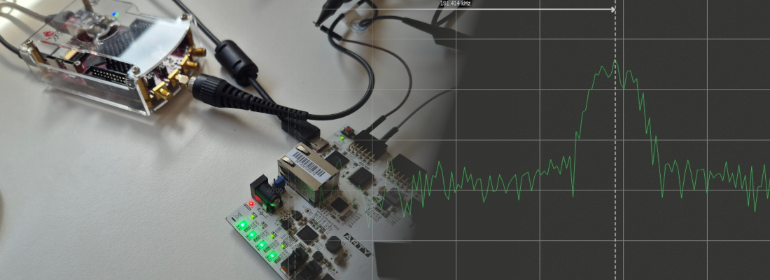
Before start this post, I have implement the project in Vivado to be sure that the project works, and make what I expect. When the bitstream is load into the Arty A7, the output of the DAC is the next.

The signal is purely a white noise, so something went wrong. After spend some time investigating, and verifying with the scope all the signals, I discovered this.

The I2S DAC driver I designed, write the data in the falling edge, to allow the DAC read the date in the rising edge, but in this case, the data is been written in the rising edge, so the DAC reads with a delay of 1 bit, reading in the MSB always a ‘0’. Since the signal is formatted in 2’s complement, if the MSB is ‘0’ means that the number is always positive, but the rest of the bits are still formatted in 2’s complement, so the output is indeed a white noise. The part of the code in charge to write the data is the next.
/* data shift */
always @(negedge sclk)
  if (!resetn)
    sdout <= 1'b0;
  else
    sdout <= data2send[data_counter];
This code, although it works in Vivado, can be written better, since the signal sclk is not a real clock, but is a prescaled clock. I have rewrite the code, using an edge detector, and using a real clock in the sensibility list. The new code is the next.
/* sclk_edge counter */
always @(posedge aclk)
  if (!resetn)
    sclk_edge <= 2'b00;
  else
    sclk_edge <= sclk_edge + 2'b01;

/* data shift */
always @(posedge aclk)
  if (!resetn)
    sdout <= 1'b0;
  else
    if (sclk_edge == 2'b11) /* negedge detector */
      sdout <= data2send[data_counter];
With this change, the error is fixed, and the data update is made in the falling edge.

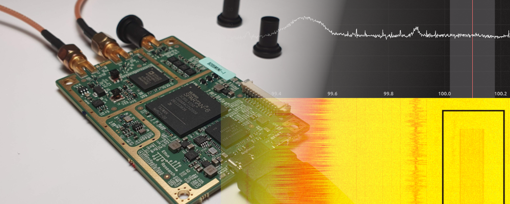
Now, I have test the project using the signal generator and the scope of the ADP5250, and this is the result.

The signal looks very good now. The next is check the volume control using the four switches that has the Arty board to verify that the amplitude changes according a binary value. To verify that we can use the persistence function.

At this point we have a (little) project implemented with open source tools, which is great. Regarding the changes I made in the code, on the synthesis process you have to learn how you have to write your code according the synthesizer that you are using, because although there ir a Verilog Standard, is up to the synthesizer tool fix possible mistakes, or even the way that the synthesizer and the place&route tool optimize the code.
Although F4PGA and the X-Ray project are advanced in terms of development, they need developers to continue growing and implementing new functions. If you want to collaborate you can enter here and contribute your bit.