Getting started with Microchip’s FPGA Icicle Kit and PolarFire SoC.
In these rare days when getting a development board with a new FPGA is increasingly difficult, a new board has come into my hands. The board is the Icicle Kit, a Single Board Computer (SBC) from Microchip Technology. It is based on their PolarFire® SoC FPGA, the latest device released by Microchip that includes a PolarFire FPGA and 5xRISC-V cores, 1xRV64IMAC, named E51, and 4xRV64GC (G= IMAFD) named U54. The E51 runs up to 667 MHz and is used as a monitor core used to perform the boot of the device. On the other hand, the U54 core is the application core, also running at 667 MHz.
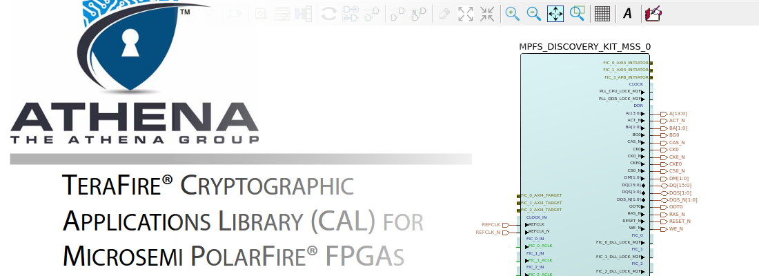
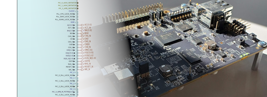
Both cores have access through the AMBA switch to all the peripherals in the Microcontroller Subsystem (MSS), and also to the fabric via 4 Fabric Interface Controllers (FIC), 3 of them configured as 32/64 bits AXI interface and the FIC3 configured as 32 bits APB interface through an AXI to APB block.

Also, there is a 4th FIC that is used to communicate the cores with a Crypto processor included in the MSS.
Regarding the fabric side, there is a big jump between Microchip’s SmartFusion® 2 SoC that we already saw in this blog, and the PolarFire SoC. In terms of logic resources, in SmartFusion2 family, we can find devices from 6k logic elements up to 146k, while the PolarFire SoC family starts with 23k up to 460k. The device in the icicle Kit is the MPFS250T, which has a total of 154k logic elements.
In terms of DSP capabilities, the element that will improve the performance of any algorithm is the MACC modules (Multiply-Accumulator). In the MPFS250T, we have 784 MACC with a multiplier of 18×18 bits and an accumulator width of 48 bits. The width of the accumulator is 4 bits greater than the MACC module of the SmartFusion2 SoC, which is not a big difference, but this will let us to save some MACC elements in some cases.
If we take a look at the Icicle Kit board, we can see a big silver IC that is the PolarFire SoC, and also a big silver socket for an SD card. The board, as I said in the beginning, is designed as Single Board Computer, so we have 2 Gigabit Ethernet interfaces, that use an SGMII protocol with the PolarFire SoC, 4 user LEDs and 4 user push buttons, a socket for MIKROE Click Boards™ (without ADC), a Raspberry PI 40 pin compatible connector and also a PCIe x16 socket, with 4 lanes connected that are ideal to connect an M.2 NVME SSD through a PCIe adapter. Regarding the memory, it has 8GB eMMC that can be used to store a Linux® distribution and is multiplexed with the SD card, 1Gb SPI Flash memory and 2GB LPDDR3 with a bus width of 32 bits.
Once we know the elements of the Icicle Kit, we are going to update the hardware and the software of the board. As we have seen, the PolarFire SoC has several elements that need to be programmed or configured. First of all, we need to configure the FPGA in order to add all the elements to manage the hardware in the board like the DDR, the Ethernet Phytter or PCIe socket. At the time of this post, the last version available in the PolarFire SoC’s Github is 2021.11. It is important to know that all the elements of the PolarFire SoC must be updated to the same version, so first of all, we will download and configure the FPGA with version 2021.11. We can download the project from the Icicle Kit Reference Design repository. The FPGA design is downloaded as a script. To create the project we have to run the script from Microchip’s Libero® Design Suite.

On the opened window, we must select the script downloaded. The script accepts some arguments in order to configure the board to perform some tests. In this case, we want to create a design without any of those configurations, so we won’t use any argument.

When we click on RUN, different IPs will be downloaded in case they are not in our host yet, and the smart design will be created.

Now we can execute all the design flow until RUN Program Action in order to generate the bitstream to configure in the FPGA. To program the board, we have to connect the USB to the connector j33, which is located on the top–right of the board.

The next element that we have to update is the Monitor Core E51. This core runs the Hart Software Services (HSS), that are a series of services to start the entire system. These services include copying from the NVMe or SD to the DDR, passing messages between cores or creating a payload containing multiple applications to be booted and run. The HSS can be downloaded from the Github repository. This time, if we navigate to the releases menu, we can download all the source files of the HSS ready to be compiled and programmed. Since we won’t change the HSS code for the moment, we can download the .job file with the HSS compiled. This /job file also includes the configuration of the FPGA, so we can go directly to this step if we do not want to change either the HSS or the FPGA design.

To use the job file to program the PolarFire SoC, we need to use the FlashPro Express software that has been installed with Libero software. Once inside the application, we have to Create a New Job Project and select the downloaded .job file.

With the corresponding file selected, we can execute the action and we will update the HSS and the FPGA at the same time. Once the HSS is programmed with the correct version, we can update again the FPGA in case we need to make changes in the SmartDesign.
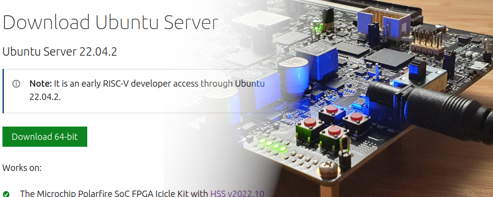
At this point, we have the PolarFire FPGA update to the last version, now we have to download the Linux image. In the PolarFire SoC Github we can find two different versions of the Linux image, one built with Yocto, and the other one built with Buildroot. Since both versions will run in the icicle Kit, the packages included in each one, and the steps to build the image are different.
For the Yocto image, we can download the SD card image from here. Once the image is downloaded, we have to write the image on an SD card. In Linux, we can do this with the next command.
pablo@friday:~/Desktop$ zcat core-image-minimal-dev-icicle-kit-es-20211208131041.rootfs.wic.gz | sudo dd of=/dev/sdb bs=4096 iflag=fullblock oflag=direct conv=fsync status=progress
[sudo] password for pablo:
1870372864 bytes (1.9 GB, 1.7 GiB) copied, 672 s, 2.8 MB/s
457065+0 records in
457065+0 records out
1872138240 bytes (1.9 GB, 1.7 GiB) copied, 672.512 s, 2.8 MB/s
Being /dev/sdb the SD card. Once the SD card is written, we can insert the SD card into the icicle Kit socket, and turn on the board. To verify the start process of the board, we have to connect a USB cable to the J11 USB connector (near the MikroBus™ socket) This USB connection will create 4 different COM ports in the computer. Port number 0 is corresponding with the Monitor Core and will show the start-up process. Port number 2 will be managed by the Linux image running in the quad-core U54, and it is a terminal to show and send commands to the Linux image. When we turn on the board, the HSS will show the Boot process. We can see that the version of the HSS is 0.99.26, which is corresponding with 2021.11, and finally, the SD card is detected and it will copy the file from the SD card to the RAM memory.

Once the boot process is finished, we can see in port 1 the Linux kernel running. At this point we have the Linux distribution running in the Icicle Kit. When I arrived at this point, I tried to use the devmem command, which is very useful to read and write data to the FPGA peripherals connected to the processor through AXI4 or APB, but in the default settings of this distribution, this instruction is not available.

The solution will be compiling my own Linux distribution with Yocto. To do this, I have followed the steps that you can find in the PolarFire SoC Yocto repository. To compile the Linux distribution, I created a virtual machine with Ubuntu 20.04, 4 cores and 12GB of RAM memory. With this configuration, the Linux building takes more than 8 hours to complete all the steps. This is a long time, so I checked the Buildroot distribution, to try to save some time.
This distribution can be found in the PolarFire SoC GitHub in this repository. In this repo we cannot find the output file of the compilation, so we need to follow all the steps to build the Linux distribution with Buildroot, which includes downloading the PolarFire SoC Buildroot SDK, and also all the linked repositories. You can find all the steps in the readme file. Finally, we have to write the image on an SD card, insert the SD card in the Icicle Kit socket, and turn on the board. Port 0 will show the same as the Yocto building distribution, but the Linux kernel will be some different, and something more important, this distribution includes the devmem command.

At this point, we have the Icicle Kit completely updated to the new version and we can start to develop. The next will be to design a Verilog module and integrate it in the reference design in order to use it from Linux.