Audio equalizer based on FIR filters.
Digital signal processing can be used in almost all engineering fields, from seismology, to obtain the distance where an earthquake has been generated, to data science, but these areas use digital signal processing as a way to obtain real interest data. On the other hand, in this post, we will talk about audio processing, an area that works directly with the waves, and is based on modifying the wave itself to obtain different effects. I am not going to explain what is sound because Wikipedia has a great explanation, but I will explain how to acquire sound signals, the protocols used, and how to design a simple equalizer to modify the amplitude of different frequency bands built with some FIR filters.
First of all, we need to read (listen), the audio signal. In general, we will work with signals that previously have been converted to an electrical signal, either using a microphone with an amplifier, the signals that are generated by an electric guitar, or simply signals that are generated by a processor. In any case, an audio signal will be an AC signal composed of many different frequencies, that all together generate the corresponding sound.
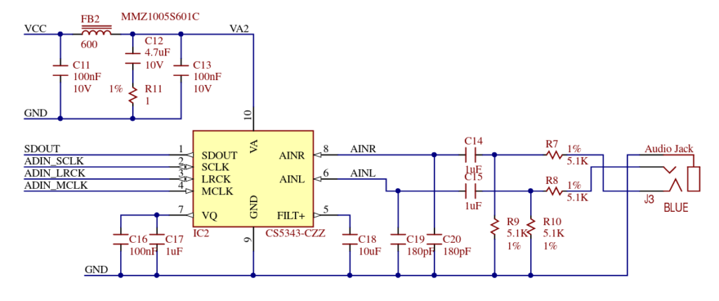
As usual, to acquire an electrical signal we have to use an ADC. In this blog, we have used different ADCs with different numbers of bits, or different sample rates, but all these ADCs are in the group of general purpose ADC. In order to read audio signals manufacturers like Analog Devices or Texas Instruments have specially designed ADC to acquire audio signals. This ADC has usually 24 bits of resolution and is designed to acquire signals at standard audio sampling rates like 44 ksps, 96 ksps or 192 ksps. These sample rates have been selected according to the bandwidth that the human ear can acquire, which starts at 20Hz to 20kHz, so according to the Nyquist theorem, we will need at least twice of frequency to acquire a signal without data loss, so the lower frequency that an audio ADC can be acquired must be at least 40ksps. Since the sample rates needed to acquire audio signals are very limited, compared with a standard ADC that can acquire up to 500ksps or 1Msps, the cost of this kind of ADC is also lowest than others, finding ADCs from 2 dollars. On the other hand, if we want to process the audio signal, we need to acquire the signal with an ADC, process the signal, and then we need to return the signal to its original state. For this purpose, we will need a DAC. Same as the ADC, there are special DACs to be used in audio applications, with similar characteristics to ADCs, that is, resolution of 24 bits, and sample rates of 44ksps, 96ksps and 192ksps. For this project, I will use the Digilent’s PMOS I2S2. This PMOD features a Cirrus ADC CS5343, with 24 bits of resolution and a sample rate up to 108 ksps. To synthesize the signal, this PMOD also includes a DAC Cirrus CS4344, a DAC with 24 bits of resolution, and sampling rate of up to 200 ksps.
The protocol used to read the acquired signal by the ADC, and also to write the corresponding signal to DAC, is Inter IC Sound (I2S). I2S is a protocol designed to transfer digital sound through different devices. The protocol is based on 4 lines, one for the system clock (MCLK), which is used for the delta-sigma modulator/demodulator, another clock for the communication (SCLK), a third clock that is corresponding with the sample rate (LRCK). This clock is a prescaled clock from SCLK. Finally the data signal (DATA). I2S is a protocol that is designed for stereo signals, which that means in any sample, a signal for right and left speakers has to be sent. For this reason, the data signal is a double data rate (DDR) signal with the LRCK signal.
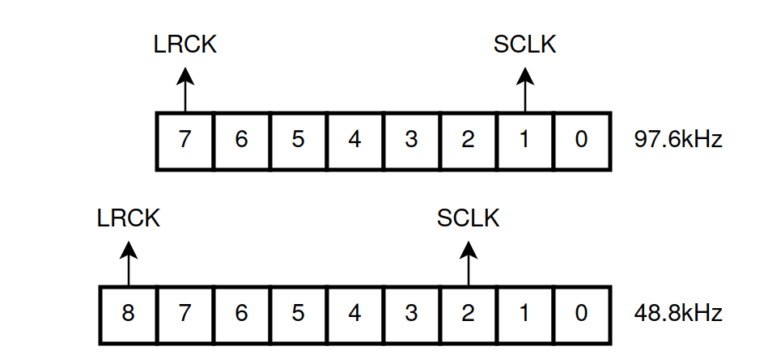
For this project, I have designed 2 different modules, one to transmit data through I2S, and the other to read data through I2S. In both cases, the module shares all the clocks and prescaler logic, with the only changes in the read and write data line. Both modules work with AXI4-Stream protocol with a data width of 64 bits (dataL + 8 bit padding + dataR + 8 bit padding). With this configuration, the relation between SCLK and LRCK is 64. The module is designed for a 25MHz clock and is ready to run at 3 different speeds, 48kHz 97kHz and 194kHz, according to the width of the prescaler. Notice that the speed of 194 is out of the range of the ADC, so this mode has to be disabled in the ADC.
assign lrck = pulse_counter[7]; /* change to 8 for 44kHz, 7 for 96kHz, 6 for 192kHz */
assign mclk = aclk;
assign sclk = pulse_counter[1]; /* fixed to 64 counts per lrck cycle. Change to 2 for 44kHz, 1 for 96kHz, 0 for 192kHz */
Next you can see the result of the simulation of the I2S module.
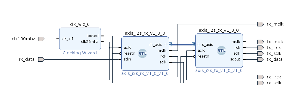
With these 2 modules, we can design a simple bridge to verify the behavior of both modules. The script to generate this block design is available on Github.
When you implement this design, you will notice that the volume when the audio signal passes through the bridge has decreased. This happens because of a divisor that you can find in the PMOD I2S2, in the ADC input. In order to compensate this attenuation, you can shift the left and the right signals one position to the left to add a gain of 2 to the bridge.
At this point we have a way to acquire and synthesize the audio signals, now is the turn of the processing. In this post, we are going to develop a 3-band equalizer. An equalizer is a device that can apply different gains according to the frequency of the signal, for example, if we need out audio signal travels a long distance, we will have no problem with low-frequency signals since they can travel long distances easily, but high-frequency signals suffer a high attenuation with the distance, so we will need to amplify high frequencies, and maybe attenuate low frequencies. Another example could be the use of different speakers, and the equalizer has to send to each speaker the frequencies that can reproduce, low frequencies for the woofer and high frequencies for the tweeters. In any of these examples, we need to split the signals according to its frequencies, and then amplify or attenuate each group of frequencies according the use of the signal. The equalizer we will design will have 3 different bands, the Bass band, for frequencies between 1Hz and 800Hz, the Medium band for frequencies between 800Hz and 3000Hz, and the Treble band for frequencies between 3000Hz and 8000Hz. We could add a fourth band from 8000Hz to 20000Hz, but in general, frequencies above 5kHz have small amplitudes and only the harmonics of some instruments can achieve this frequency, so for this example, we only equalize up to 8000kHz.
Now, in order to split the audio signals in these 3 different bands, we have some options, perform a DFT and then delete all the components we don’t need and finally perform an inverse DFT to synthesize again the signal, or use filters like FIR or IIR. The first option is not optimal for real-time audio processing, since the time spent in the DFT computing will be translated into a pause in the output signal, which is not desirable. To perform real-time audio processing the best option are filters. We know 2 different kinds of digital filters that can help us to split the signal, FIR filters and IIR filters, and here comes the heavy part of this project. The advantages of using IIR filters are many, starting for the high attenuation that we can achieve with low-order filters. Also, if we need narrow bands, these filters are also the best choice, but this time there is another player in the field, the group delay.
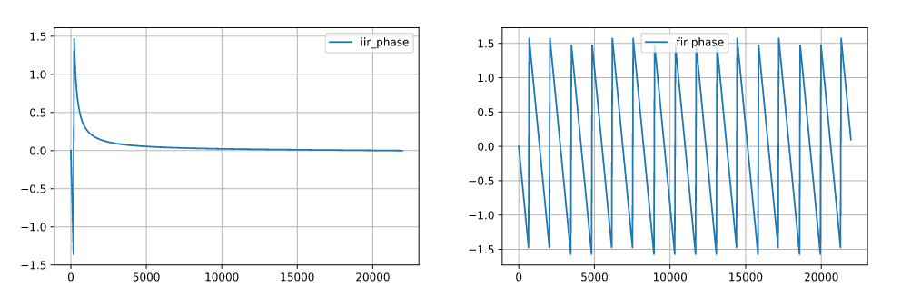
Mathematically, group delay can be defined as the derivative of the spectral phase of the filter, practically, group delay is the delay in samples for each frequency. Imagine you have a copper wire with a length of L. If we connect one side of the wire to a function generator and apply to the wire a signal of 100Hz, the signal spent a T second to arrive on the other side of the wire. In case we apply a frequency of 1kHz, the signal will spend the same amount of time, T seconds. We can say that the wire has a group delay of T seconds, in other words, has a constant group delay so is a linear phase system. If instead of a wire, we have an IIR filter and we apply the same signals, we will see how the amount of time that the 100hz signal spends to arrive on the other side is different than the 1kHz signal. This will cause in some moments, the input frequency components will be different than the output components. I the case of audio signals, where the signal in a sum of different frequencies, this could be a problem, for example, if we are processing a guitar chord, where different frequencies will produce a particular sound, this sound will be different in the output of our algorithm. This effect will provoke a distortion in the audio signal. So, can not we use IIR filters in audio systems? Obviously, there are solutions for almost all problems, but for now, we will change the way we will split our audio signal.
As we said before, and you sure know, there are other kinds of digital filters, the FIR filters. This filter has, like the IIR filters, advantages and disadvantages. As disadvantage, we will need a very high order filter to achieve the attenuation we will need to design a narrow band equalizer. Also, high-order filters, cause a high amount of operations must be performed, and this is translated in time. On the other side, they are very easy to design, they are always stables and, they have a linear phase, in some cases.
The cases where the FIR filters have linear phase are where the coefficients are symmetric, and luckily, this condition is not hard to accomplish. In fact, respective FIR design functions of MATLAB or Python design by default symmetric FIR filters, so this means that, with its disadvantages, we can design an audio equalizer with FIR filters without generating a distortion in the signal. For symmetric FIR filters, the group delay is N/2 samples.
Once we have decided which kind of filters we will use, we have to design the filters with any tool. In my case I used Python. You will notice that the different bands have a little gap between them. These gaps will cause signal attenuation in those bands, but they can be corrected by applying a gain on the corresponding band. Also, if we allow a high cross-band between filters, will be hard to amplify, for example only the bass band, or the mid-band.
Regarding the design of the filters, they are designed with 33 taps, and for the bass and mid, I have used a square window to improve the attenuation. This will cause a ripple in the mid-band. For the treble band, I used a Hanning window.
Regarding the HDL design of the filter, I have designed a new FIR filter that takes advantage of the filter symmetry to perform half the operations. The coefficients of a symmetric FIR filter accomplish the next rule:
\[b_i=b_{N-i}\]Using this, we can perform half of the multiplications if we add previously the corresponding samples. An example of 4th order FIR filter is shown in the next figure.
The filter designed has 16 coefficient inputs to implement a 32nd order FIR filter. The previous addition adds the 2 corresponding samples, except when the index is equal to 16 since only one sample is added.
/* macc operation */
assign input_bn_temp = (index == 16)? input_pipe[index]: (input_pipe[index]+input_pipe[32-index]);
assign input_bn = input_bn_temp * bx_int[index];
The top module of the equalizer will be built by the I2S transmitter and receiver, and 3 pairs of filters for the right and the left channels. A gain will be applied to the output of the filters in order to manually equalize the output.
Audio signals are a very good option if you are starting with signal processing for some reasons. First, you don’t need a signal generator since any smartphone, MP3 player or computer can generate an audio signal, also, both MATLAB and Python have packages to read and process .wav files, so you can check your DSP algorithm. Also, you can use your microphone input to verify the behavior, and of course, you can also verify your algorithm and experiment with it by simply listening to the output. I spent the past 2 weekends exploring different kinds of equalizations and has been very interesting.
You will notice that the equalizer we have designed here is very simple, and in most cases, we will need more performance in terms of filtering. I will explain this with an example. The next image is a collection of the frequency spectrum of a song. The image is obtained by dividing a song into different windows and then performing the DFT of each window.
We can see how the major part of the harmonics are located below 1kHz, and the harmonics above 3khz are very small. That means, we will need narrow-band filters to split the frequencies, and this is hard to get with FIR filters. In the next posts, we will see how we can equalize IIR filters to obtain a linear phase, at least in the pass band. Keep connected!


