Using IIO to manage an ADC from Petalinux.
Managing an ADC is something that any engineer dedicated to signal processing has to do very often. This task, in general, use to be no much complicated, unless you are using a high-speed ADC with LVDS interface or something similar, but that kind of ADCs are not the scope of this post. In this post, I will show you how we can manage an ADC from Petalinux in less than 10 minutes. I said that I will show you to manage an ADC, but this process will be valid to manage ADC, DAC, gyroscopes, accelerometers… and a large list of different devices. I am talking about compatible industrial IO (IIO) devices, that has native support from Linux kernel.
According the definition of Industrial IO on https://www.kernel.org
The main purpose of the Industrial I/O subsystem (IIO) is to provide support for devices that in some sense perform either analog-to-digital conversion (ADC) or digital-to-analog conversion (DAC) or both (…) Usually these sensors are connected via SPI or I2C. A common use case of the sensors devices is to have combined functionality (e.g. light plus proximity sensor).
Drivers to manage these devices can be manually added to the Linux kernel, or in case the device we are using is one of the devices included on the kernel by default, we only need to add the corresponding entry to the device tree, and include the drivers on the kernel configuration. In this case, I will use a controlpaths board based on an ADC of Texas Instruments which is natively supported by the kernel, ADC122s021. If we search this ADC on the supported ADCs on the kernel.org web page, we notice that the ADC is not supported, but we can find an equivalent ADC, in terms of protocol. In this case, we can find that ADC128s052 is supported, and this ADC is part of the same family as the ADC122s021, which means the SPI protocol to manage one is the same as the other. Also, if we open the .yaml file, we can see a list of supported ADC, in which it appears the ADC122s021.
In order to develop this project, we can use any board where we can install Linux. In my case, I am going to use the Picozed 7015 board with the FMC Carrier Gen2. This board is based on xc7z015 SOC device.
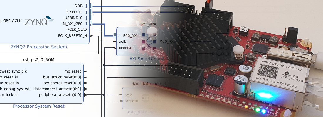
To start this development, first, we have to create a new project on Vivado, and create a new block design. On this block design, we have to add only a Zynq Processing System. According to the board you will use, you will have access to the SPI pins of the PS or not. In my case, SPI pins are used by other peripherals, so if I want to use the SPI0 bus of the PS, I have to use EMIO to pull the pins out through the PL. On the tab MIO Configuration, we will search the peripheral SPI 0 (SPI 1 can be used as well), and configure the IO to EMIO.

Done that, on the Zynq PS block in the block design, we will have available all the pins of the SPI0 peripheral. Next, we have to connect these pins to external ports, and later, on the xdc file, we will assign the corresponding pins of our board. As you can see, the block design in this case is pretty simple.

When we develop a driver for an ADC, we choose the frequency of the SPI and is easy to synthesize accurately a desired frequency. In this case, we are limited by the PS clocking system. To manage the clock of the SPI, we have to select the frequency of the clock that is connected to the SPI peripheral. Output SCK frequency will the frequency of the clock of the SPI peripheral, divided by a power of 2 from 1 to 128. That is, for a clock of 166.666 MHz, if we want an SCK frequency of 2 MHz, the best approximation we can achieve will be 166.66 MHz/128 = 1.3MHz. You can find more information about clocking on UG585, pg698. In this case, I will select a frequency of 166.666 Mhz.

Next, as always, verify the block design, generate the wrapper, generate the bitstream and export the hardware to use it on the Petalinux build process.
Once the Petalinux project has been created, next we will import the hardware exported on Vivado.
petalinux-config --get-hw-description ../../../xilinx/picozed7015_petalinux/
Now, we will modify the device tree to tell the kernel that there is an ADC122s021 connected to the SPI0 (or SPI1), and connected to the SS 0. This has to be configured on project-spec/meta-user/recipes-bsp/device-tree/files, on the file system-conf.dtsi, by adding the next lines.
/include/ "system-conf.dtsi"
/ {
};

&spi0 {
status = "okay";

        adc@0 {
            compatible = "ti,adc122s021";
            reg = <0>;
            spi-max-frequency = <2000000>;
        };
    };
Notice that the SPI frequency is set to 2 MHz, but this is an unreachable clock frequency with our configuration, so the clock will run at 1.3 MHz.
The next step is to add the corresponding drivers to the kernel. To do that we have to make this.
petalinux-config –c kernel
After a while, a new terminal window will be open, and we will navigate to Device Drivers > Industrial I/O support > Analog to digital converters and select the line corresponding with the ADC we are going to use, in my case Texas Instruments ADC122S021.

Once we have the kernel configured and the device tree modified, last is build our Petalinux distribution.
petalinux-build
Once Petalinux is built, I use to package all the files and copy them to an SD, but in this case, we will run Petalinux in a different way, through the JTAG. This method is very useful if we are debugging our system and we want to avoid the process of extracting SD, replacing files, and inserting SD again. Also, as the JTAG is connected, we can use an ILA to debug our design. To boot Petalinux through the JTAG, first, we have to configure the PL.
petalinux-boot --jtag –fpga
Next, we have to fill all the corresponding memory locations with the u-boot and the Linux kernel itself.
petalinux-boot --jtag –kernel
Done that, Petalinux must boot without issues. Once inside Petalinux, we will navigate to /sys/bus/iio/devices. On this folder we can find 2 devices. Device number 1 is corresponding with the XADC integrated on the Zynq part, and device0 will be our ADC. To check that, we will enter to iio:device0 folder, and check the content of name.
>> cat name
adc122s021
If we check all the content of the folder we can see several files and folders. Interesting files to us are in_voltagex_raw, which returns us the value read on each channel. In this case, I have connected a 2v source on channel 0, and my supply voltage is 3v, so the result will be 2/3*2^12 = 2730.
Notice that the driver is compatible with the ADC128s052, that is an 8 channels ADC, but the ADC I use has only 2 channels, so if I try to read channels from 2 to 7, the value returned by the ADC will be 0.

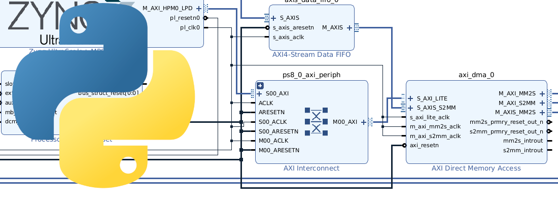
Industrial IO is a very interesting bus in which we can manage different kind of devices in a very simple way. There are a lot of devices supported natively by the kernel, from ADC to PMICs, that makes very easy to develop applications to manage them. If you think this bus is powerful, imagine developing your drivers mixing the configuration of a device like an ADC from Petalinux, and generating a high-speed interface on the PL, dumping readings to DDR via AXI Stream. In addition to this, from a host PC, MATLAB reading data from DDR and use it as input to Simulink algorithm.
Although I never talked in the blog about IIO, we have used it to manage the USRP B205 Mini on this post, where the IIO bus is managed by the host PC through a USB 3.0 interface.