Eclypse Z7, ZMODs and SYZYGY.
 Eclypse Z7
Few months ago, Digilent presented their new development platforms based in Zynq and Zynq US+, with connectors compatibles with SYZYGY standard. This standard is in the middle between PMOD and FMC, with the enormous advantage that can be soldered by makers, with a solder, and some patience.
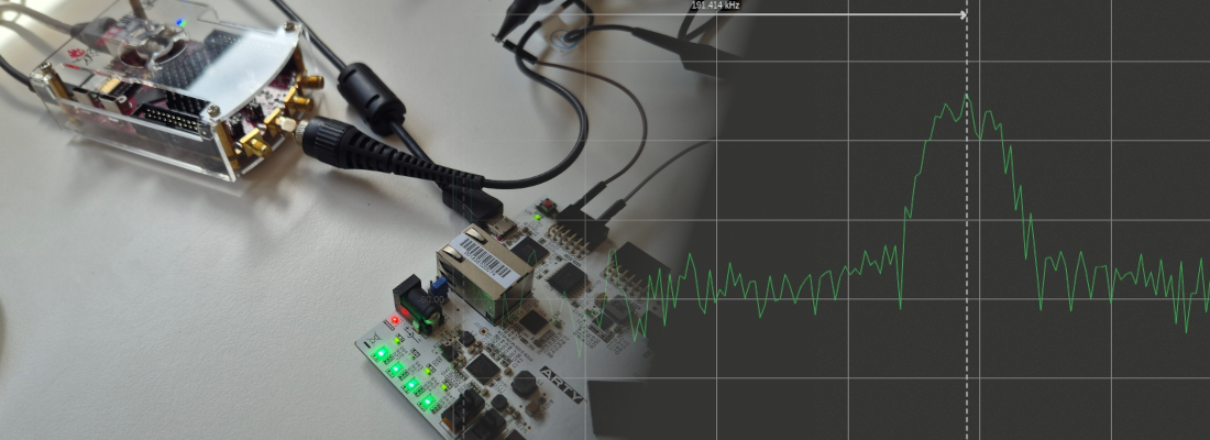
Eclypse Z7 hardware.
First of all, let’s see the hardware we have. The brain of the board is an XC7Z020, maybe the most popular SOC of Xilinx. The board also have 2 leds, 2 push buttons, ethernet, RAM, more leds, ….. but, the important, 2 SYZYGY connector. SYZYGY is a emergent standard that, as I said before, try to fill the gap between FMC and PMOD, offering up to 500MHz in the standard choose by Digilent, and 28 single-ended signals, including 8 differential signals. Also includes 2 differential clock lanes, and, like PMC, a configurable VIO.

When I saw for first time this standard, first that comes to my mind was medium/high speed ADC and DAC, and those are one of the purposes of this connectors. Configurable VIO is also a very interesting, since we can configure for each device we connect, the supply, and the interface voltage. This configuration has to be saved in the peripheral board inside a memory, or, like the ZMODs, inside an ATMEL microcontroller. This information is readed by the Platform MCU on the Eclypse Z7, and this MCU configure one PMIC per connector. This PMIC give the corresponding voltage to the device, and the corresponding FPGA bank. This way, both supply and interface levels are the correct.

ZMOD peripherals.
Digilent, with the Eclypse Z7 board, also launched 2 ZMOD periperals, one with a 125Msps, 14 bits ADC AD9648, and one with a 125Msps, 14 bits DAC, AD9717. Each of those devices has a SPI bus for configuration, and in the case of DAC, one 14 bits bus for DDR data, and in the case of the ADC, the chip has 2 14 bits buses for each channel, but only one is connected to the Zynq, so, by configuration, we have to configure that the 2 channels will be read through only one data bus, in DDR mode.
The configuration has no other mystery than read datasheet and send the correct configuration registers, but, for me, work with DDR channels is pretty new. First of all, FPGA has to supply clock for 2 devices, single-ended for the DAC, and differential for the ADC. For do this you can read my post about DDR resources on the 7 series, because this is an example of clock forwarding, and according the output buffer we choose, we have a differential output, or single ended output. The code for the differential output is the next.
/* Clock forwarding for ADC. Differential clock */
ODDR #(
.DDR_CLK_EDGE("SAME_EDGE"),
.INIT(1'b0),
.SRTYPE("SYNC")
)ODDR_CLKADC(
.Q(clk50mhz_ddr), /* Output clock the the output buffer */
.C(clk50mhz), /* Input clock to the DDR primitive */
.CE(1'b1),
.D1(1'b0),
.D2(1'b1),
.R(rst),
.S(1'b0)
);

OBUFDS #(
.IOSTANDARD("DEFAULT"),
.SLEW("SLOW")
) OBUFDS_CLKADC (
.O(o_adc_clkout_p), /* Output clock to the ADC */
.OB(o_adc_clkout_n), /* Output clock to the ADC */
.I(clk50mhz_ddr)
);
Then, we have to serve data to the ADC and DAC also with a DDR format, so all data pin has to pass through the DDR primitives for ensure minimum jitter.
/* Output data */
generate for(genvar i=0; i<=13; i=i+1)
  IDDR #(
  .DDR_CLK_EDGE("OPPOSITE_EDGE"),
  .INIT_Q1(1'b0),
  .INIT_Q2(1'b0),
  .SRTYPE("SYNC")
  ) IDDR_ADCDATA (
  .Q1(o14_data_a[i]), /* Channel A data */
  .Q2(o14_data_b[i]), /* Channel B data*/
  .C(i_dco), /* Output clock */
  .CE(1'b1),
  .D(i14_data[i]), /* Output data */
  .R(rst),
  .S(1'b0)
  );
endgenerate
The key of the management of those devices are in the lines above. ZMOD also has several relays to configure output/input voltage range or coupling, but like SPI register, read and configure.
I am very exited with this board because for one project I need a DAC and ADC in the same board, and although I need more resolution than 14 bits, and less speed, I am happy because with this features I can play with anti-aliasing filters and oversampling to increase the resolution and test all the theory behind this practices.