Exploring the Cordic algorithm.
Many years ago, the processors were slow, and they only can compute additions and, spending some time, multiplications. Calculating division was a hard task, and no mention trigonometric operations and square roots. As low resources makes the people smarter, in 1959, Jack Voelder created an algorithm capable of performing trigonometric operations only using additions and shifts. The algorithm was based on rotating vectors, and the algorithm was named COordinate Rotation DIgital Compute, or Cordic. Lets take a look to the mathematics behind Cordic.
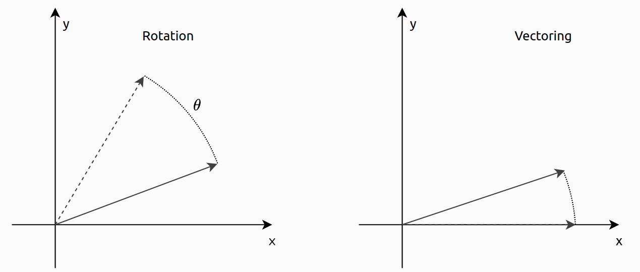
Cordic is an efficient digital technique to rotate vectors. The word “efficient” is very well used since the operations needed are only additions and shifts. It is important to mention that Cordic is an approximation, unlike the FFT, that is an optimization. That means that the results obtained will have an error, but the error can be as little as most iterations are used. First of all, we are going to review the original rotation equations.
\[x’=x_0 \cdot cos(\theta) – y_0 \cdot sin(\theta)\] \[y’=y_0 \cdot cos(\theta) – x_0 \cdot sin(\theta)\]These equation can be rearrange so that.
\[x’ = cos(\theta)(x-y \cdot tg(theta))\] \[y’ = cos(\theta)(y+x \cdot tg(theta))\]At this point we have a gain that is \(cos(\theta)\), and a equation that depends of the \(x\) and \(y\). The gain, can be rewrite as follows.
\[cos \theta = \frac{1}{\sqrt{1+tg²(\theta)}}\]Now we have an entire equation that depends of \(x\), \(y\) and the tangent of \(\theta\). The key of the Cordic algorithm is that if we select only angles that their tangent will be negative powers of two, this operation will be a right shift. Replacing the terms in the above equation, the resulting equations are the next.
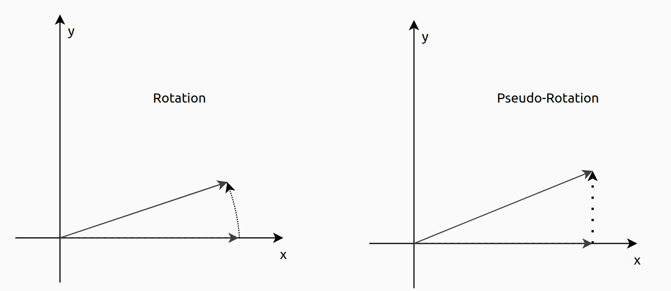
\[x_{k+1} = x_k – y_k \cdot d_i \cdot 2^{-i}\] \[y_{k+1} = y_k + x_k \cdot d_i \cdot 2^{-i}\]Notice that the gain that we had before, has been removed, and we will talk of that gain later. Now, we can see the effect of eliminate the gain, will produce that the length of new vector will be greater than the original, since \(\sqrt{1+tg²(\theta)} < 0\). For that reason we say that the Cordic algorithms performs pseudo-rotations instead of rotations. In the next figure you can see the difference.
Also, in the resulting equations, a d term will be added. This is used to rotate the vector in one direction or the other one. Its value will be 1 or -1, and their value will be computed in each iteration. To obtain its value, a third equation will be added to the system.
\[z_{k+1} = z_k – \cdot d_i \cdot tg^{-1}(2^{-i})\]\(z\) will be the angle accumulator, and making an performing and accumulation will store the total rotation, so if I want to rotate a vector, I have to initialize the angle accumulator to the desired angle, and then, making it zero, the rotation will be completed. Therefore, the value of d will be dependent of the sign of z. In the z equation appears the term \(tg^{-1}(2^{-i})\). To obtain this arc tangent, we will use a look up table that will store the different values of the arc tangent. The number of elements stored will be the same as the number of iteration we will perform. In general 10 or 12 iterations will be enough for almost any case
\[d = -1 \,\, if \,\, z_i <0 \,\, otherwise \,\, d = 1\]The Cordic algorithm that is used to rotate a vector from one angle to another is named rotation mode. There is another way to use Cordic, and is names vectorization mode. This kernel will rotate the vector until it is aligned to the x axis, that is the same as the y = 0. This time we will use the value of y to obtain the sign of the rotation.
\[d = 1 \,\, if \,\, y_i <0 \,\, otherwise \,\, d = -1\]The angle accumulator, in the vectoring mode will store the initial angle of the vector.
\[A_n= \prod_{i=0}^{N-1}\frac{1}{\sqrt{1+2^{-2i}}} \approx 1.646\]Notice that the equation will be stable in the value of 1.646, so we can store that gain, as a process gain, and apply it when we will need the real angle.
As Cordic is an approximation, and some simplifications are done, the explained above is only valid when the vector is in the first quadrant. This limitation can be solved applying a transformation before the algorithm will be executed, so that storing the original quadrant, and move the vector to the first, we can later apply a simple change in the resulting values.
Once the theory is clear, lets implement the algorithm first in MATLAB to check how easy is to implement. The Cordic algorithm is an iterative algorithm, so the entire algorithm will be inside a for loop. In the code below I have added the quantization for a width of 16 bits and a fractional of 13, since the angle can range from \(-2\pi\) to \(2\pi\).
for i = 0:n_iterations-1
    if znc < 0
        xnc = fi(xnc_1 + bitsra(ync_1, i), nT);
        ync = fi(ync_1 - bitsra(xnc_1, i), nT);
        znc = fi(znc_1 + atan_lut(i), nT);
    else
        xnc = fi(xnc_1 - bitsra(ync_1, i), nT);
        ync = fi(ync_1 + bitsra(xnc_1, i), nT);
        znc = fi(znc_1 - atan_lut(i), nT);
    end

    vnc = xnc + ync * j;

    xnc_1 = xnc;
    ync_1 = ync;
    znc_1 = znc;

    An = An * sqrt(1+2^(-2*i));
end
As we saw before, the algorithm only uses additions and shifts (bitsra command performs a right shift). Also, I have included the iterative calculation of the process gain, that is 1.646 for 10 operations.
Regarding the implementation in Verilog, I have created a generic module that contains the Cordic kernel for rotation. The inputs are the initial values of the two vectors (x, y), the initial value of the angle accumulator, and also the address and data for the LUT that contains the tangent of \(2^{-i}\). Making this external will allow that the number of iteration will be configurable. Notice that the width of the input and output can be different than the value of the phase, since they are not related, and we don have to make any operation between them.
module axis_cordic_kernel_rotation_v1_0 #(
  parameter inout_width = 16,
  parameter phase_width = 18,
  parameter cordic_niter = 16,
  parameter cordic_niter_width = 4
)(
  input aclk,
  input resetn,

  /* slave axis interface */
  input signed [inout_width-1:0] s_axis_real_tdata,
  input s_axis_real_tvalid,
  output s_axis_real_tready,

  input signed [inout_width-1:0] s_axis_imag_tdata,
  input s_axis_imag_tvalid,
  output s_axis_imag_tready,

  input signed [phase_width-1:0] s_axis_phase_tdata,
  input s_axis_phase_tvalid,
  output s_axis_phase_tready,

  /* atan look-up-table */
  output [cordic_niter_width-1:0] atan_lut_address,
  input signed [phase_width-1:0] atan_lut_data,

  /* master axis interface */
  output reg signed [inout_width-1:0] m_axis_real_tdata,
  output reg m_axis_real_tvalid,
  input m_axis_real_tready,

  output reg signed [inout_width-1:0] m_axis_imag_tdata,
  output reg m_axis_imag_tvalid,
  input m_axis_imag_tready,

  output reg signed [phase_width:0] m_axis_phase_tdata,
  output reg m_axis_phase_tvalid,
  input m_axis_phase_tready
);
Then, the Cordic algorithm itself is implemented as an finite state machine (FSM) with five states. The state 1 is where the comparative is performed, the states two and three are equivalent but each one have a different sign, and finally, the state four will set the data valid signals and write the output registers.
case (cordic_state)
  3'd0: begin
    if ((s_axis_real_tvalid || s_axis_imag_tvalid || s_axis_phase_tvalid) &&
    (s_axis_real_tready && s_axis_imag_tready && s_axis_phase_tready)) cordic_state <= 3'd1;
    else cordic_state <= 3'd0;

    real_tdata_temp <= s_axis_real_tdata;
    imag_tdata_temp <= s_axis_imag_tdata;
    phase_tdata_temp <= s_axis_phase_tdata;
    iteration <= 0;

    m_axis_real_tvalid <= 1'b0;
    m_axis_imag_tvalid <= 1'b0;
    m_axis_phase_tvalid <= 1'b0;
  end
  3'd1: begin
    if (phase_tdata_temp[phase_width-1]) cordic_state <= 3'd2; /* phase < 0*/
    else cordic_state <= 3'd3;


  end
  3'd2: begin /* phase < 0 */
    if (iteration == (cordic_niter-1)) cordic_state <= 3'd4;
    else cordic_state <= 3'd1;

    real_tdata_temp <= real_tdata_temp + (imag_tdata_temp >>> iteration);
    imag_tdata_temp <= imag_tdata_temp - (real_tdata_temp >>> iteration);
    phase_tdata_temp <= phase_tdata_temp + atan_lut_data;

    iteration <= iteration + 1;
  end
  3'd3: begin /* phase > 0 */
    if (iteration == (cordic_niter-1)) cordic_state <= 3'd4;
    else cordic_state <= 3'd1;

    real_tdata_temp <= real_tdata_temp - (imag_tdata_temp >>> iteration);
    imag_tdata_temp <= imag_tdata_temp + (real_tdata_temp >>> iteration);
    phase_tdata_temp <= phase_tdata_temp - atan_lut_data;

    iteration <= iteration + 1;
  end
  3'd4: begin
    cordic_state <= 3'd0;

    m_axis_real_tdata <= real_tdata_temp;
    m_axis_imag_tdata <= imag_tdata_temp;
    m_axis_phase_tdata <= phase_tdata_temp;
    m_axis_real_tvalid <= 1'b1;
    m_axis_imag_tvalid <= 1'b1;
    m_axis_phase_tvalid <= 1'b1;
  end
endcase
Until here, we have seen that aim of the Cordic algorithm is rotate vectors, but changing the initial values of their inputs we can use Cordic to make other cool things, for example, we can compute sines and cosines. Lets take a look to the original rotation equation.
\[x’=x_0 \cdot cos(\theta) – y_0 \cdot sin(\theta)\] \[y’=y_0 \cdot cos(\theta) – x_0 \cdot sin(\theta)\]Now, we are going to initialize the x0 to one and y0 to zero. The resulting equations are the next.
\[x’=x_0 \cdot cos(\theta)\] \[y’=x_0 \cdot sin(\theta)\]Using these initialization values with the rotation kernel (has no sense to use the vectoring kernel since we do not want to make the y zero), we will obtain in the resulting x, the cosine of the angle, and in the resulting y, the sine of the angle. The angle will be define in the angle accumulator, that will have a final value of zero.
The following figures are the results of 3 simulations with 3 different angles, and the sine and cosine values computed by the Cordic algorithm implemented in the FPGA.
The Cordic that I have implemented does not include the gain, so for each result we need to apply the gain 1/1.646.
Cordic algorithms also works with hyperbolic trigonometrics, so we can obtain the hyperbolic sine and hyperbolic cosine in the same way as we did with sine and cosine.
The rotation equations for the hyperbolic kernel are the next.
\[x_{k+1} = x_k + y_k \cdot d_i \cdot 2^{-i}\] \[y_{k+1} = y_k + x_k \cdot d_i \cdot 2^{-i}\]Regarding the angle accumulator, this time the hyperbolic tangent is used.
\[z_{k+1} = z_k – \cdot d_i \cdot tgh^{-1}(2^{-i})\]To perform a rotation of vector we have the rotation hyperbolic kernel.
\[d = -1 \,\, if \,\, z_i <0 \,\, otherwise \,\, d = 1\]To turn the vector to the x axis, we have to use the vectoring hyperbolic kernel.
\[d = 1 \,\, if \,\, y_i <0 \,\, otherwise \,\, d = -1\]The process gain also changes with respect the cordic kernel.
\[A_n= \prod_{i=1}^{N}\frac{1}{\sqrt{1-2^{-2i}}} \approx 0.8\]Notice that the value of A_n, for i = 0 is zero, so the final product will be zero, so the iterations will start in 1.
The hyperbolic vectoring kernel is very used to compute the square root of a value. The initialization values to obtain the square root of , are the next.
\[x0 = a + 0.25\] \[y0 = a – 0.25\] \[z0 = 0\]The phase input z is not used in the vectoring kernel.
Initializing with this values, the output of the Cordic algorithm is the next:
\[x_N = \sqrt{(a+0.25)^2 – (a-0.25)^2}\] \[y_N = 0\]In the x output, the 0.25 constant is compensate so the result is the square root of a. The implementation of the hyperbolic vectoring kernel is similar to the rotation kernel with some changes in the sign. The next results shows how the Cordic kernel compute the square root of some values.
There are some considerations when we are using the hyperbolic kernel. The first one is that the kernel only works without error in a range of 0.5 to 2, so we will need to extract a constant from the value we want to compute the square root, and apply it as a gain after the Cordic algorithm finish. The other consideration is that the hyperbolic kernel may be unstable. The solution to this instability is repeat some iteration twice. The iterations are i = 3*i+1, starting on i = 4, so we will need to repeat the iterations 4, 13, 40… As I mentioned before, 10/12 iterations will be enough for almost all the calculations.
Although, as I did, you can implement your own Cordic kernel, Xilinx and Microchip has its own IPs to perform trigonometric operations, or compute the square root. Those IPs are based in the corresponding Cordic kernel, either rotating or vectoring, and according the operation you need to perform, the input and the outputs are multiplexed to x, y or z.
Cordic were designed to make slow and limited processors capable to perform trigonometric calculations. But not only is used to compute sines and cosine, we have seen that we can use the algorithm to compute, for example, the square root. To do that we only have to initialize the 3 inputs with an specific value. ST has a Design Tip very interesting with many initialization combinations and the results that we can obtain. Now a days, even the smallest processors that are inside a calculator have a high compute power, so these algorithms could be forget, but the need of high efficient devices, and the increase of the speed, make algorithms like Cordic widely used.


