Ripple suppression circuit for PWM DAC.
If we are working with analog signals, is very common that we will need an analog level for set an offset if we are working with a bipolar signal, or maybe we will need an analog level to set a threshold. In these cases, the theory says that we will need a digital to analog converter, or DAC. DACs are integrated circuits that outputs an analog voltage according the digital value that we send from a digital IC like an FPGA or a DSP. In the market there are many types of DAC, and according the speed we need, or the accuracy needed in the analog value, we will choose the correct DAC that fits all our requirements.
In cases where the analog signal that we can obtain will be a low-frequency signal or a DC signal, the cheapest method that we can use comes from the communication world, and is based in modulate the signal to obtain from a digital signal, an analog signal. The modulation that we will use is named Pulse Width Modulation (PWM).
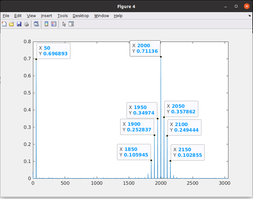
When we modulate a signal, we will add to the original signal a significant amount of harmonics. In the next frequency spectrum, we can see the harmonics when we modulate a 50Hz signal with a 2000 Hz square signal using PWM.
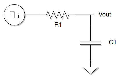
In order to obtain the DC level of the PWM signal generated with the FPGA, we usually will use an RC filter circuit. This circuit is built with only 2 components, a resistor and a capacitor. The circuit is a 1st order filter, so we know, the attenuation is only 20dB/dec. In the cases where the PWM frequency is much higher than the cut frequency, all the harmonics generated by the PWM will be attenuated, remaining only the low-frequency signal, and obviously, the DC level. In case that the frequency of the PWM signal will be close to the cut off frequency of the filter, harmonics of the PWM will pass through the filter to the output, generating a ripple in the output signal. As the frequency of the PWM signal increases with respect to the cutoff frequency, the peak-to-peak ratio of the ripple will be reduced.
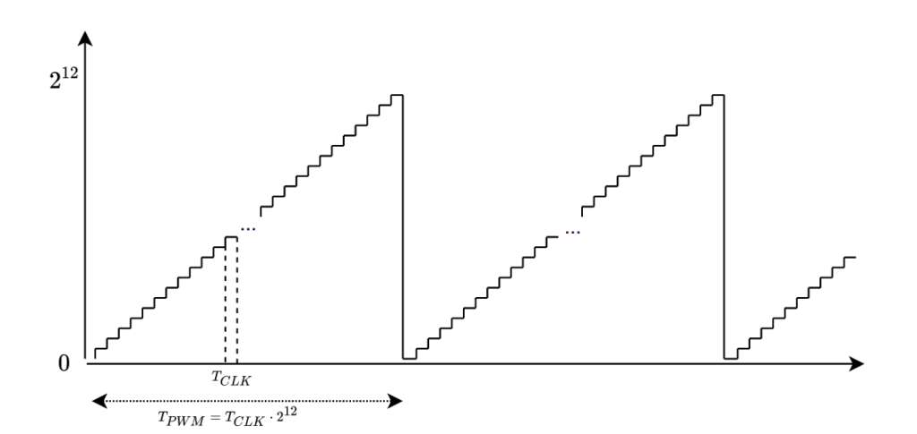
At this point, the solution is easy, and we have no one but two different solutions. The first one is to increase the PWM frequency several decades above the cutoff frequency of the filter, but this have another problem, the resolution. I will show you in the next figure.
If we want to have a resolution of n bits, the total amount of the counts of the ramp used to generate the PWM signal will have at least 2^n points. With this data, we can obtain the PWM frequency as 2^n time the period of the clock used to generate the ramp. If we need to increase the period of the PWM signal, we have two options, the first one, increase the frequency of the clock, which is not possible in many cases since the clock will be the same for all the region in case that we are using an FPGA, and the second one, reduce the number of counts that the ramp has to complete, that is corresponding with a loss of the resolution.
Since increasing the PWM frequency seems not a good option in many cases, to improve the quality of the DC signal generated, we can design the RC filter in order to decrease the cut-off frequency as much as we need, making sure that the interesting band has no attenuation. This option will be interesting in many cases, but decrease the cut-off frequency of the filter, also will increase the settling time, and this handicap can make that the change of the offset that we are generating will be late, so the signal can be clipped.
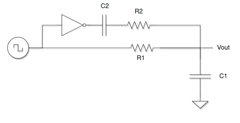
To overcome these limitations, the EDN web page published a very interesting solution. The solution is based on adding a second PWM signal that is the negated of the original and passing this signal through a high pass filter. Then, the new signal and the original will be added and filtered with a low-pass filter. The idea was to add the inverse of the ripple to the filtered signal, in order to reduce the ripple in the output signal.
To test this solution, I have designed a PWM module that generates a PWM signal of 2 kHz. In the top module 2 different PWM signals are wired, one is the output signal of the module, and the other one is the negated. Using a double output, if we can, we can save the inverter. IN the case that we cannot double the PWM output, we can use a NOT gate, or use a BJT transistor in common emisor mode in order to negate the output.
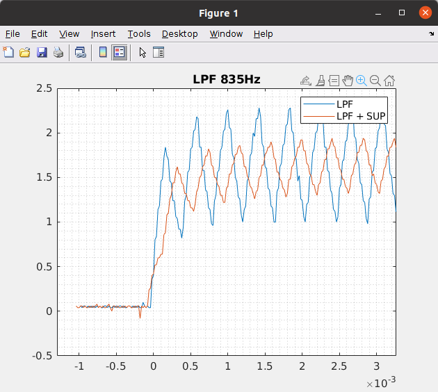
In the first test, the RC filter is configured for a cut-off frequency of 835 Hz. The blue signal is the PWM filtered only with the low pass filter. The blue signal is the output when the high pass filter is also connected. The values of the high pass filter are designed to the half frequency of the low pass, that is 417 Hz. We can see that the amplitude of the ripple is reduced significantly.
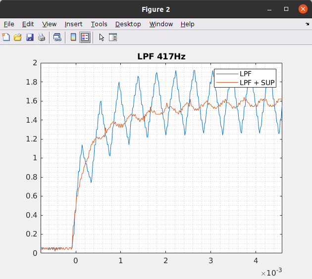
In the second test I changed the value of the RC filter to configure the cut-off frequency at 417Hz, the same frequency as the high pass filter. IN this case, we can see that the ripple is reduced when we are using only the low pass filter, that is what we have to expect since we are attenuating harder the high-frequency harmonics. When the high pass branch is connected, we can see how the ripple is quite reduced. This is the best case that I get.
If I set the frequency of the high pass filter higher than the low pass, the ripple when the high pass branch is connected is increased significantly, so the circuit does not work properly.
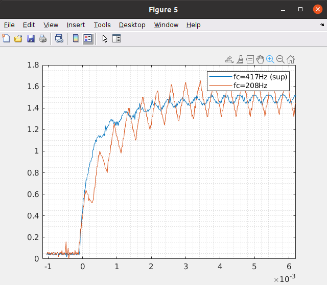
Regarding the settling time, in the next figure, I have compared the outputs of the 417Hz configuration adding the ripple suppression branch, and a 208 Hz configuration without using the ripple suppression. We can see that we can achieve a fast response with less ripple amplitude by using this solution.
The components added to the circuit, and the increase in the BOM cost, make this method very interesting for many projects where we have to generate a DC signal. Also, if we are using a device that can generate a PWM signal and its negated, we can save the inverter, so using 2 more components, the results are worthwhile. But this method has its limitations. It works great to generate DC signals that, in certain cases, we will need to suddenly change and we cannot allow a large delay, but if the signal that we need is a sine signal, my choice will be always a DAC, even a cheap one. As always, I have shown you a tool, and you as engineers must decide where this tool can be useful.


