True random number generators based on FPGA

 CryptoLite
In cybersecurity, random numbers are extremely important, and the security of some cryptographic algorithms depends directly on the quality of the random numbers generated.
Typically, random numbers are produced using software algorithms. However, these are not truly random—they are pseudo-random numbers. This means that although the values may appear unrelated to each other, their behavior can be predicted if the internal state of the algorithm is known. This predictability is not always a disadvantage: during the debugging phase of an algorithm, it is often useful to reproduce the same conditions multiple times in order to identify and fix potential issues.
However, when working on a device that is intended for production, we no longer benefit from the predictability of pseudo-random numbers. In such cases, we need an algorithm capable of generating high-quality random numbers, or in other words, we need a true random number generator (TRNG).
The quality of random numbers is directly tied to entropy. Entropy is a fundamental concept in this field—it measures how unpredictable a system is. Examples of entropy sources include the thermal noise of an integrated circuit, metastable states in flip-flops, and clock jitter in phase-locked loops (PLLs).
Due to the hardware architecture of FPGAs, they are particularly well-suited for generating true random numbers, as they naturally contain several exploitable sources of entropy. In this article, we will explore the design and implementation of TRNGs using FPGAs, and examine how different entropy sources can be harnessed effectively.
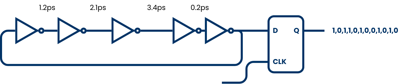
The circuit we are going to use to generate true random numbers is the ring oscillator.

A ring oscillator is a digital circuit consisting of an odd number of inverter gates connected in a closed loop. Due to its topology, the circuit cannot settle into a stable logic state, which causes it to oscillate continuously between logical high and low. The oscillation frequency depends on the propagation delays through the logic elements and routing paths. These delays are subject to physical phenomena such as thermal noise, electromagnetic interference, temperature fluctuations, power supply noise, manufacturing variations and even the purity of the slicon used for the piece. These factors introduce timing jitter, which becomes a valuable source of non-deterministic entropy.
The output of the ring oscillator is sampled using a stable system clock. Because the oscillator and the sampling clock are asynchronous, and due to the natural jitter in the oscillator signal, the sampled bits can contain unpredictable variations. This effect is enhanced by combining multiple independent ring oscillators using XOR gates, or by applying debiasing algorithms to improve statistical randomness.
The implementation of a ring oscillator in Verilog is quite straightforward. Initially, I implemented a single 5-stage ring oscillator. However, the results were not as good as expected, since the generated numbers exhibited a high occurrence of 0x55 and 0xAA patterns. This behavior is due to a correlation between the natural frequency of the ring oscillator and the clock frequency of the output register.
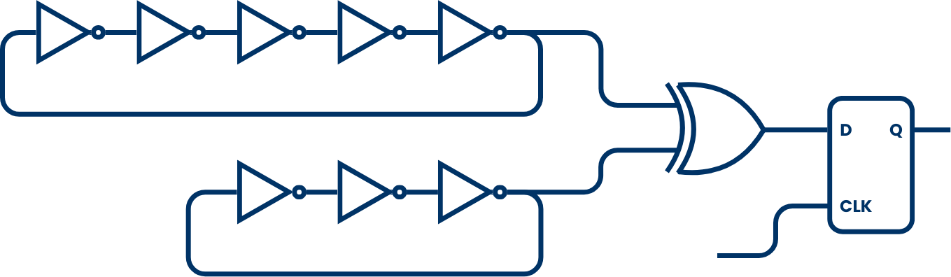
To eliminate this correlation, several options are available. One approach is to sample the ring oscillator output using a non-periodic clock. However, this option complicates the overall design. As an alternative, I implemented two different ring oscillators with different numbers of stages, ensuring that each has a distinct natural frequency. The outputs of both oscillators are then XORed to produce the final random bitstream.
We must consider that the ring oscillator structure may generate metastable states, which are generally undesirable. However, in this case, they are actually a necessary part of the design, as they contribute to the entropy source.
To instruct Vivado not to optimize or modify the ring oscillator logic during synthesis, we need to add the dont_touch attribute to the wires or instances involved in the ring oscillator.
(* dont_touch = "true" *) wire [4:0] ring_bits5; // ring ascillator signals
(* dont_touch = "true" *) wire [4:0] ring_bits3; // ring ascillator signals
Additionally, in the constraints file, we need to ensure that our design allows combinational loops. This can be done by adding the following lines to the XDC file.
## Allow combinatorial loops for TRNG5
set_property ALLOW_COMBINATORIAL_LOOPS TRUE [get_nets trng_inst0/ring_bits5[4]]
set_property ALLOW_COMBINATORIAL_LOOPS TRUE [get_nets trng_inst0/ring_bits3[2]]
The following code shows the implementation of the two ring oscillators used in the design.
// Ring oscillator 5 stages
assign ring_bits5[0] = ~ring_bits5[4];
assign ring_bits5[1] = ~ring_bits5[0];
assign ring_bits5[2] = ~ring_bits5[1];
assign ring_bits5[3] = ~ring_bits5[2];
assign ring_bits5[4] = ~ring_bits5[3];

assign random_bit5 = ring_bits5[4];

// Ring oscillator 3 stages
assign ring_bits3[0] = ~ring_bits3[2];
assign ring_bits3[1] = ~ring_bits3[0];
assign ring_bits3[2] = ~ring_bits3[1];

assign random_bit3 = ring_bits3[2];
Finally, this code generates the synchronous part of the design. It includes a shift register used to build a 32-bits register that stores the generated random value.
This module produces a new 32-bit random value every 32 clock cycles, while the random_data_ready signal is set.
// Random number generation logic (placeholder for actual TRNG logic)
always @(posedge aclk) begin
  if (!resetn) begin
    random_data_reg <= 32'h0;
    bit_count <= 6'd0;
    random_data_valid <= 1'b0;
  end else begin
    if (bit_count == 6'd32) begin
      random_data_valid <= 1'b1; // Indicate that random data is ready after 32 bits
      random_data_output <= random_data_reg; // Output the generated random data
      bit_count <= (random_data_ready)? 6'd0: bit_count; // Reset bit count
    end
    else begin
      random_data_reg <= {random_data_reg[30:0], random_bit3^random_bit5}; // Shift in new random bit
      bit_count <= bit_count + 6'd1;
      random_data_valid <= 1'b0; // Data not ready until 32 bits are collected
    end
  end
end
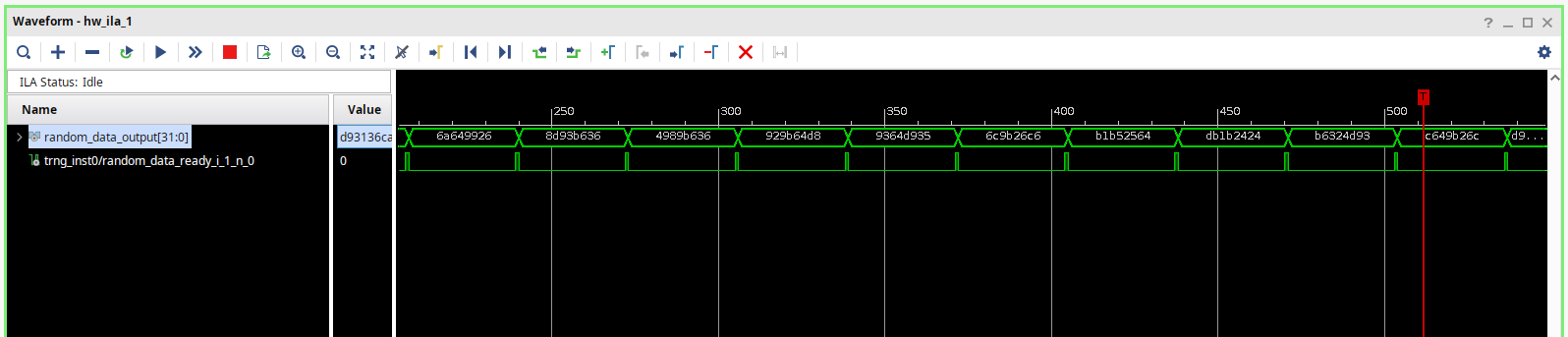
The behavioral simulation of this design will produce a constant value in the output of the ring oscillator. To verify correctly this design we need to implement the design, and using a ILA to verify the values generated. The following figure shows the ILA results.
In order to evaluate the quality of the random bits generated, the National Institute of Standards and Technology (NIST) provides a set of statistical tests designed to verify the rondomness of the values generated, the Statistical Test Suite (STS).
For example, the randomness could potentially be enhanced by adding an additional ring oscillator and XORing its output with the existing ones, which would increase entropy and reduce correlation.
If you are interested on this field, I’ll be at the Crypto Privacy Village at DEF CON 33 giving the talk Reconfigurable HSMs: Future-Proofing Hardware Security Against Evolving Threats, about how FPGA will be very important in the future of cybersecurity. If you can not be there, the talk will be recorded to be uploaded later to YouTube.