Working with Kria SOM.

 KR260
KR260
In this blog, we already talk about the kit KR260 in this post. In that post, we used the KR260 to implement an acceleration design. The cost and the power of this development board make it a very interesting board to deploy Zynq MPSOC designs. If we compare its cost, around 350$, with the cost of another Zynq MPSOC development boards, it is almost ridiculous, considering that we cannot find a Zynq MPSOC board for less than 1000$. On the other side, the KR260 has a limited number of IO ports, and does not have an FPGA Mezzanine Card (FMC) connector, but it has a great advantage. The KR260 is not a development board, is a kit based on a Kria SOM, and a carrier board, so if we need more peripherals, we can develop a custom carrier board, but wait makers, it is not an Arduino Nano. The KR260 uses two high-density connectors of 4 rows each one with a total of 240 connections, 480 pins in total. In this document you can find considerations to design custom carrier boards.
Although they look the same, the first Kria kit released by Xilinx, the KV260, has a different SOM with only one of these connectors, reducing significantly the number of pins. Both the KV260 and the KR260 are focused on AI applications, the first of them for artificial vision application, and the second one for robot control and also artificial vision but, essentially, the SOMs of the KV260 and the KR260 are Zynq MPSOC based boards with up to 4 GB of RAM, so there is no problem if using them as a “normal” development boards (with some differences on the boot). In this post, we are going to prepare a base project to use the KR260 to deploy a “regular” design.

The boot of the KR260
I mentioned that, although it is a board based on a Zynq MPSOC, when we connect the SOM to the carrier, the boot process is fixed by resistors, so we cannot select how the Zynq device will boot. The device selected by default is the QSPI memory.

I am not sure what is the reason for this, but the KR260 has a primary boot process, which is executed before the First-Stage Bootloader (FSBL). This primary boot searches between the available boot devices, and runs when detects a valid one. The key is that this primary boot has updates, so we need to keep this program updated in order to be able to run newer versions of Petalinux (which is in the 22.2 version yet… and it is not compatible with Ubuntu 22.04…). This process is quite similar to the Hart Software Services used in Microchip’s PolarFire SOC.
If we use the Kria SOM with a custom carrier board, I am quite sure that this limitation disappears, since in this case, the MODE pins of the SOM are available to be connected wherever we need.
Basic HW design.
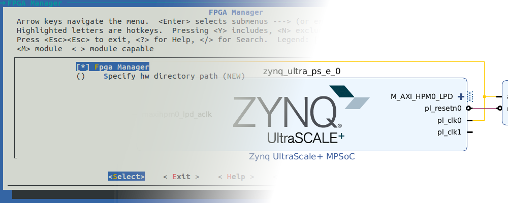
Now that we know a little bit more about the KR260 and the Kria SOM, let’s start with the HW design. In the design I am going to create, I am going to use just the Processing system (PS). Then, enabling the FPGA Manager in the Petalinux configuration, we will be able to load different designs for the peripheral Logic (PL), as we made here with the TE0802.
As usual, the first we have to do is create a new project in Vivado. After selecting a name for the project and the sources, if needed, we have to select the device we want to use. Since the KR260 is from AMD, the board file can be downloaded directly from Vivado using the board repository. Once the board is available to be selected, we can select the carrier board we are going to use by configuring the connections of each connector. For this design we are going to use the Robotics Starter kit, so we will configure the connections for the connectors 1 and 2.

If we are going to develop a design using only the Kria SOM, we can let this option without configuration since we will connect the peripherals in the block design according our carrier board configuration.
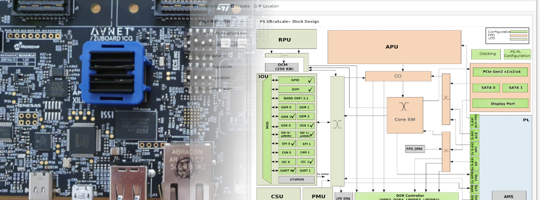
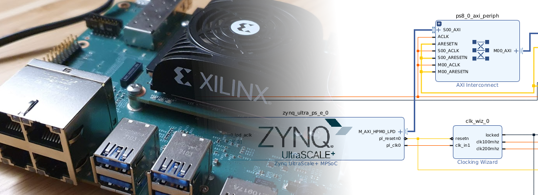
Once the project is created, we can generate a new block design. In this design, we are going to include just the Zynq MPSOC. If we want to use other peripherals, later we can configure the PL using the FPGA Manager. It is important enabling the AXI Master ports in order to, later, can use them in future PL designs.

When the Zynq MPSOC is added to the Block Design, we can execute the Block Automation to apply the default preset.
When the configuration is applied, we can take a look at the peripherals enabled on the ARM.

At this point, it is important to have the connections configured in the board selection. If we do not have the board connections configured, when applying the PS default preset, the peripherals will not be enabled.
In addition to the peripherals enabled in the PS, the board has a bunch of them connected to the PL. Peripherals like 2 Gigabit Ethernet ports, PMODs, LEDs and the SFP are connected to the PL. These peripherals can be automatically connected to the PL dragging them from the Board tab to the Block Design.

If we want to use the Gigabit Ethernet interface, we are going to need to use the Tri-mode Ethernet MAC, which is under a free license, but you have to download and install it. The license can be downloaded from this link.
Now, when the HW design is complete, we can generate the bitstream and export the hardware. Also, I am going to change the name of the folder of the HW design to hw.
SW design.
The next step is creating the Petalinux distribution. First, we need to add to the PATH the corresponding folder. To do that we can execute the script located in the Petalinux installation folder name settings.sh.
pablo@friday:~/workspace_local/te0802_ptlnx$ source /media/pablo/data_m2/xilinx/PetaLinux/2022.2/settings.sh
PetaLinux environment set to '/media/pablo/data_m2/xilinx/PetaLinux/2022.2'
WARNING: /bin/sh is not bash!
bash is PetaLinux recommended shell. Please set your default shell to bash.
WARNING: This is not a supported OS
INFO: Checking free disk space
INFO: Checking installed tools
INFO: Checking installed development libraries
INFO: Checking network and other services
WARNING: No tftp server found - please refer to "UG1144 2022.2 PetaLinux Tools Documentation Reference Guide" for its impact and solution
Now, as usual, we are going to create the project, that in my case is named kr260_base_ptlnx. Then, I will change the name of that folder to os, in order to separate the hw configuration from the os and keep both in the same folder.
pablo@friday:~/workspace_local/kr260_base$ petalinux-create --type project --template zynqMP --name kr260_base_ptlnx
pablo@friday:~/workspace_local/kr260_base$ mv ./kr260_base_ptlnx ./os
pablo@friday:~/workspace_local/kr260_base$ cd ./os
Next, we are going to configure our distribution, as well as indicate the .xsa file generated by Vivado using the command petalinux-config.
pablo@friday:~/workspace_local/kr260_base/os$ petalinux-config --get-hw-description="../hw"
In this configurator, we need to enable the field FPGA Manager.

When Petalinux is configured, we can package all using the command petalinux-package.
pablo@friday:~/workspace_local/kr260_base/os/images/linux$ petalinux-package --boot --uboot
[INFO] Sourcing buildtools
INFO: Getting system flash information...
INFO: File in BOOT BIN: "/home/pablo/kr260_base/os/images/linux/zynqmp_fsbl.elf"
INFO: File in BOOT BIN: "/home/pablo/kr260_base/os/images/linux/pmufw.elf"
INFO: File in BOOT BIN: "/home/pablo/kr260_base/os/images/linux/bl31.elf"
INFO: File in BOOT BIN: "/home/pablo/kr260_base/os/images/linux/system.dtb"
INFO: File in BOOT BIN: "/home/pablo/kr260_base/os/images/linux/u-boot.elf"
INFO: Generating zynqmp binary package BOOT.BIN...


****** Xilinx Bootgen v2022.2
  **** Build date : Sep 26 2022-06:24:42
    ** Copyright 1986-2022 Xilinx, Inc. All Rights Reserved.


[INFO]   : Bootimage generated successfully

INFO: Binary is ready.
WARNING: Unable to access the TFTPBOOT folder /tftpboot!!!
WARNING: Skip file copy to TFTPBOOT folder!!!
Notice that the image generated before has not a .bit file loaded, so the design only uses the PS.
When all the boot image is generated we can copy them with the root file system and the Linux kernel image to an SD card. The SD card has to contain two different partitions, one for the boot files, and the other one for the root file system. The partition where the boot is located has to be formatted using the FAT file system, and the partition for the root file system has to be EXT4. I have used the application disks to generate the partitions.

In the boot partition, we need to copy the boot.scr, BOOT.bin and image.ub files. On the other partition, we need to extract the content of the compressed file rootfs.tar.gz.
When the SD card is ready, we can insert it into the KR260, and power-up the board.
Booting the KR260.
When the USB is connected to the computer since the board has an FT4232 IC, four different UART ports will be generated. The port connected is the UART1, so we will need to open this port. Then, we will see the BOOT of the board.
If you remember few lines above, I mentioned that the board is preconfigured by resistor to read always first the QSPI memory, and this can be checked in the boot, where we can see that the boot mode is configured to QSPI 32 bit Boot Mode . The program located in this memory is given by Xilinx, and it includes a U-Boot to boot the ARM correctly configuring the peripherals but remember, the peripherals for the Robotics Starter Kit. If we use the Kria SOM in a custom carrier board, we can connect the UART to a different port, so the default configuration will be invalid.
Xilinx Zynq MP First Stage Boot Loader
Release 2022.1   Mar 22 2022  -  19:51:22
MultiBootOffset: 0x40
Reset Mode	:	System Reset
Platform: Silicon (4.0), Running on A53-0 (64-bit) Processor, Device Name: XCZUUNKNEG
QSPI 32 bit Boot Mode
FlashID=0x20 0xBB 0x20
�NOTICE:  BL31: v2.6(release):v1.1-9205-gec5dccc32
NOTICE:  BL31: Built : 06:15:49, Mar 22 2022


U-Boot 2022.01 (Mar 21 2022 - 14:42:10 +0000)

CPU:   ZynqMP
Silicon: v3
Detected name: zynqmp-smk-k26-xcl2g-rev1-sck-kr-g-rev1
Model: ZynqMP SMK-K26 Rev1/B/A
Board: Xilinx ZynqMP
DRAM:  4 GiB
PMUFW:	v1.1
Xilinx I2C FRU format at nvmem0:
 Manufacturer Name: XILINX
 Product Name: SMK-K26-XCL2G
 Serial No: XFL1F2MCFBJ4
 Part Number: 5057-04
 File ID: 0x0
 Revision Number: 1
 ...
The Xilinx program, at the end of the process, will search for a valid device for booting the custom firmware. This program makes this initializing the USB, and then scanning the devices one by one. When one of them has a valid program, then the program switch to this device. This can be found when the terminals shows Found U-Boot script /boot.scr.
starting USB...
Bus usb@fe200000: Register 2000440 NbrPorts 2
Starting the controller
USB XHCI 1.00
Bus usb@fe300000: Register 2000440 NbrPorts 2
Starting the controller
USB XHCI 1.00
scanning bus usb@fe200000 for devices... 5 USB Device(s) found
scanning bus usb@fe300000 for devices... 2 USB Device(s) found
       scanning usb for storage devices... 1 Storage Device(s) found
Hit any key to stop autoboot:  0
model=SMK-K26-XCL2G

Device 0: Vendor: Generic  Rev: 1.98 Prod: Ultra HS-COMBO
            Type: Removable Hard Disk
            Capacity: 15193.5 MB = 14.8 GB (31116288 x 512)
... is now current device
Scanning usb 0:1...
Found U-Boot script /boot.scr
2777 bytes read in 12 ms (225.6 KiB/s)
## Executing script at 20000000
Trying to load boot images from usb0
35030492 bytes read in 2329 ms (14.3 MiB/s)
## Loading kernel from FIT Image at 10000000 ...
   Using 'conf-system-top.dtb' configuration
   Trying 'kernel-1' kernel subimage
     Description:  Linux kernel
     Created:      2022-10-03   7:50:07 UTC
     Type:         Kernel Image
     Compression:  gzip compressed
     Data Start:   0x100000fc
     Data Size:    9268952 Bytes = 8.8 MiB
     Architecture: AArch64
     OS:           Linux
     Load Address: 0x00200000
     Entry Point:  0x00200000
     Hash algo:    sha256
Finally, when our custom Linux boots, it will ask us for a user name, and to change the current password. Then, we have our device running our custom Petalinux distribution.
PetaLinux 2022.2_release_S10071807 kr260ptlnx ttyPS0

kr260ptlnx login: petalinux
You are required to change your password immediately (administrator enforced).
New password:
Retype new password:
Either the KR260 or the KV260 are kits based on the Kria Ecosystem, and, according to the Xilinx/AMD web page, new Kria SOMs are coming. I am interested in one in particular, the Kria SOM for cost-optimized applications, which seems to be based on Artix Ultrascale+, but this is not confirmed. Summarizing, FPGA and SOCs are every day more and more complex devices, with a high number of pins, and high-speed peripherals that make the design of the board for these devices too difficult. Using SOMs, this task is simplified since we only have to interface with connectors that, although in some cases are also high-density connectors, are easiest to route than a 1000 pins BGA IC with a distance between them of 0.5mm. Also, SOM manufacturers usually design carrier boards, so we can test the most we can using the carrier and then port this SOM to a custom carrier board, reducing debug time. In any case, for small quantities, SOMs are a very interesting choice.