Eclypse Z7 and xFFT.

 Eclypse Z7
When we talk about digital signal processing, 2 things come to my mind. First one is the sinc wave, used as a cover page of a lot of books about signal processing, and the second one, is the fourier transform.
Fourier transform is used for travel between 2 domains, temporally domain, where all of us are comfortable seeing our signals waving, and the frequency domain, where the signals, normally, are static, but is in this domain, where we can obtain more information about the characteristics of the signal. In this post I do not pretend explain the Fourier Transform or its variant, the Fast Fourier Transform, for that there are free books like this, or web pages like this, where you can find information. In this post I will explain how to use the xFFT IP for implement an FFT on the Digilent’s Eclypse Z7 board, but the same can be used with any 7 Series FPGA.
When we need to obtain the value of one of several harmonics, we have 2 algorithms that can help us. If the number of harmonics is low, maybe the best option will be a Goertzel filter, but when we need a high number of harmonics, or even the complete spectrum, Goertzel filters turns inefficient, so in this case, our option is DFT or FFT. In the case that we need a Goertzel filter, Xilinx has not an IP for implement it, so if we have time, we can implement a Goertzel filter. In ths case, we will use the xFFT IP from Xilinx.

We can add the xFFT from IP catalog, then we have to configure the IP. First, we have to set the number of channels and number of samples. In my case, I select only one channel because I only will use a single channel of the ADC and DAC, and 128 samples. Next is to select the architecture. There are 4 selectable architectures, Pipeline, that is a Streaming implementation, and Radix-4, Radix-2 and Radix-2 Lite, that are a Burst implementation. For the Streaming implementation, Decimation in Frequency is used, however, for Burst implementations, the xFFT uses the Decimation in Time. According the Radix selected, the number of stages vary from log2(N) for Radix-2, to log4(N) for Radix-4. Number of stages has a direct effect on the DSP48 slices used, since although the number of stages is lower in Radix4, the width of this multipliers are higher, so a higher number of multipliers will be used. Another effect of the number of stages, is the number of the scaling factors. If output scaled is used, the width of the output will be the same as the input, but internally, maybe one or several values can use more bits that the input/output have, resulting in an overflow. For avoid that, every stage can be scales by a factor of 3, 2, 1 or 0, representing the number of bits shifted. I could no found a mathematical method for select each scaling factor, and the best option for me is simulate the design with a input signal similar, or it most similar as we can, to the real signal, and ensure that with this signal, overflow is not produced, and the transformations works properly. For avoid that, we can select the output unscaled, and the output will has a high width than the input.
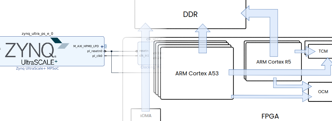
Once the IP is configured, we can talk of how communicate with it. The xFFT uses the protocol AXI-Stream, and for my design, I need a BRAM where the Harmonics are stored, and another BRAM where the output signal is stored. This second BRAM will be readed by the DAC. For di that, we can use 2 IPs availables in the IP Catalog, AXI-Datamover and AXI-FIFO. In my case, I prefer create my own module according the next diagram.

The module I’ve developed is bram2xfft2bram. This module uses 2 inferred bram, and the xFFT IP. On the input BRAM, the desired input of transformation is stored, then, once all the input is filled, from uart we can start the transformation, and the result is stored in the output BRAM. This BRAM will be readed by the DAC, and we obtain on the analog output the resulting signal.
On the other side, the module can configure the xFFT to implement a forward or inverse FFT, so if we use the input BRAM to store the analog signal captured by the ADC, we can obtain the FFT transformation. Once we have the desired harmonics, and the readed harmonics, we can compare them, and verify the bode diagram of the system.
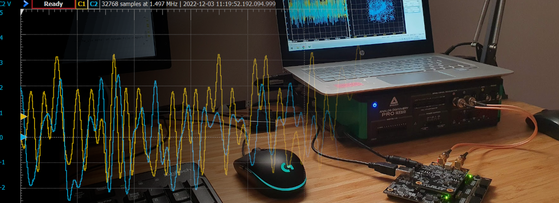
This is a simple example of the xFFT, and the speed of the ZMOD DAC and ZMOD ADC provide us a powerful signal generator and signal acquisitor. If you need more information about the bram2xfft2bram, feel free to contact me. Thanks for read 🙂